
Chapter 23 | PBR Materials

PBR Material Editing and Texture Mapping
In Virtual CRASH 6, the material properties of any polygon mesh object are adjusted via the “Material” menu in the left-side control panel. To demonstrate how to add new materials to an object, let's begin by selecting a vehicle from the Virtual CRASH assets browser that has a fully populated materials list. In either the “Elements” [Shift+E] or “Faces” [Shift+F] selection type, start by selecting the polygon faces that use the “carpaint” material from the “Material” menu. This is done by left-clicking on “carpaint” and then clicking the “Select Faces” button located beneath the material list. The “select faces” button is only visible when using the “Elements” or “Faces” selection type. All polygon faces associated with the “carpaint” material will then be selected. If materials are already present in the material list, you can simply left-click any of them, along with the “select faces” button, to select the corresponding polygon faces. However, it’s important to note that not all vehicles come with predefined materials list in this menu.
With these polygons selected, we can left-click “new” underneath the material list to assign a new default material to those polygons which were selected. Note, had we left-clicked “new” without first selected polygons, the new material would have been applied to the full vehicle mesh.
With the material selected, scroll down beneath the list, and you’ll find the Physically Based Rendering (PBR) material settings. Note, once selected, any material appearing in the materials list can be modified using the parameters discussed below.
PBR materials utilize parameters based on the physics of light and materials to ensure consistency and realism across various lighting environments. PBR materials typically include several attributes necessary in the material interface:
Albedo: Defines the surface's color in neutral lighting, without the influence of direct light or shadows.
Normal: Adds surface detail and texture without altering the object's geometry, simulating small bumps and grooves.
Metalness: Determines whether a surface behaves like a metal or a non-metal. Metals reflect all incoming light as specular reflections, while non-metals diffuse part of it.
Roughness: Controls how rough or smooth a surface appears, affecting the sharpness of reflections. A smoother surface results in clearer reflections, whereas a rougher surface scatters light, leading to diffuse reflections.
Emissive: Emissive materials emit light as if they are light sources themselves (note: they do not produce actual illumination in the scene as of the initial release of VC6), independent of external light sources. This property is useful for creating objects that appear to glow, such as screens, light bulbs, or other visual effects. The emissive property can define both the color and the intensity of the perceived light emitted by the material. When using this property, you will typically want to enable the bloom effect as well (see Chapter 2). See example below of how to apply this effect.
Opacity: Determines how transparent a material is. A material with 100% opacity is fully opaque, meaning no light passes through it, while a material with lower opacity levels will be partially or fully transparent, allowing light to pass through and making objects behind it visible.
Below we see the PBR default settings.
Below, we've increased the metalness and decreased the roughness to achieve a mirror-like finish. Experiment with the various sliders to gain a deeper understanding of how these adjustments influence the material's appearance. Remember, if you're in “Object” [Shift+O] selection mode, left-clicking “new” will create a new material for all polygons in the object’s mesh. Typically, you would want to be either in “Faces” [Shift+F] or “Elements” [Shift+E] mode to apply new materials to specific components of the vehicle.
Automatic Material creation by Mtl File
Polygon mesh objects, such as vehicles, can be imported into Virtual CRASH in obj, 3ds, and dxf formats. If the obj file has an associated mtl file sitting in the same file folder, the Virtual CRASH will parse the material specifications in the mtl file and automatically create materials. These materials can then be further customized in the material menu.
Here for example, we see a few entries from an mtl file used to define the materials for a vehicle model such as the one used above.
Automatic Texture Mapping by mtl File
A texture map assigns a color pattern via image file to the local 2D coordinate “(u,v)” space of the mesh object. As with mtl files described above, many 3D model builders also include texture map files along with the geometry. The mtl file tells Virtual CRASH which portions of the various image files are to be mapped onto a set of materials. Here we see an example mtl file, which references various jpg image files which contain the model’s texture mapping.
The texture map image files sit in the same file folder as the mtl. Note, it is typical to find the paths to the image files contained in the mtl file need to be modified to point to the image file location on your local hard drive. The easiest way to ensure the image files are found is to place the images, mtl, and obj file in the same file folder. Then simply remove the full path altogether as shown above.
Here, we see the model imported into Virtual CRASH. Note that any logo or pattern can be added by simply modifying the image files used for texture mapping. For components in the material list with a texture map applied, you will see an “x” symbol next to “albedo”, indicating that the colorization is derived from the image file. This feature can be disabled by left-clicking on the “x”.
Manual Texture Mapping
Left-clicking on “albedo” allows you to upload an alternative texture file or load the texture file if it fails to load automatically via mtl.
Creating your own texture map can be occasionally difficult since knowing how a texture will map to an object’s surface geometry is difficult to know. One way to better understand how an image will be mapped to a geometry is to use a pattern image file such as the one below.
Here we see the image mapped onto various shapes.
Image placement, orientation, and scale can be modified using the (u,v,w) scale, (u,v,w) offset, and the angle controls.
The “map method” option gives more control over how the texture map is to be placed on the surface geometry. By default, “object” is used, which wraps the image over the entire surface geometry using the (u,v) local space of the object. If “local xy” is selected, the image is projected downward along the object’s local z-axis (similar to the receive projection option). Note, the boarder pixels are stretched downward along the z-axis in the example below. Since the local option is used below, the mapping will not change as the objects move through the scene. If “world xy” is used, the image is projected downward along the global z-axis. In this case, the texture would be seen as static relative to the environment even as the object moves. Often it is easiest to use “local cube” map method.
Logos and Decals
The procedure illustrated below allows you to add a logo or emblem to your vehicle. Suppose we wish to place a logo on our truck shown below; however, our truck did not come with any pre-made texture map image files we can use as a template.
Logo embedded within texture map image
You can apply materials with custom albedo textures polygon face by polygon face using [Shift+F] to select the given face or by elements with [Shift+E]. Recall, you can use Ctrl+left-click to add to your selection and Alt+left-click to subtract from your selection. In this case, we'll also use the lasso tool since we want to apply a logo to both sides of our vehicle at the same position. So, we begin by using the lasso tool [F6] to select the polygon faces [Shift+F] where we wish to apply a logo. Remember, you can add to your selection by using Ctrl+lasso and subtract from it it by using Alt+lasso. To conclude the lasso command, right-click. Once we've selected our faces, we create a new material and apply our pattern image file as albedo (this isn’t a requirement, but it can help simplify the process).
Map Method
When the map method (found at the bottom of the material menu) is set to “object”, the truck's uv geometry results in a complex mapping. Often, opting for one of the projective views simplifies the process.
Switching to the “local xz” map method significantly simplifies the material mapping process for this scenario. It's important to note that because the projection occurs along the local y-axis direction, the image initially appears inverted. Setting the u size to -1 rectifies this issue, allowing us to accurately gauge the placement of various portions of the truck’s geometry in relation to this texture map.
If necessary, in an application like Photoshop, you can overlay your logo onto the checker pattern to visualize its placement in relation to the vehicle's geometry. Fortunately, in this instance, the mapping process is straightforward due to our use of the local xz projection mode.
If you use a checker pattern albedo file to help understand the placement of your texture, after positioning the checker pattern, you can then create a new image containing only the logo or emblem with the same pixel dimensions as the test pattern image and load it as the new albedo texture, and its alignment relative to the mesh will remain the same.
Here we have our logo centered in the final albedo texture image, with a solid white background.
Next, we load our logo by clicking the “albedo texture” button and selecting our image file.
Here we see the polygons the image was applied to.
We then copy and paste the other PBR parameters to ensure they are the same as those for the main body.
You can also try using the eyedropper for the remaining polygon material's “albedo color” property. Because the solid white background color embedded in our graphic may look different compared to this “albedo color” material property for the remaining polygons in our truck mesh, we can also create a small solid white image file to apply as an albedo texture to the rest of the vehicle. We sample a small corner of our logo graphic and apply it as albedo to the remainder of the vehicle polygons.
Here we see the polygons which had the white background image file applied as the albedo texture. Since this vehicle already had a “carpaint” material defined, the process was quick and easy.
Wrap Mode
When you're placing a logo or emblem on a vehicle, you'll need to decide what "wrap mode" to use (found at the bottom of the material menu). "Clamp" is a good option but requires you to ensure you have a clean border of pixels on the outer perimeter of your image since those will radiate outward to apply the albedo to selected polygons technically outside the image border. You also need to be more careful aligning the uv offset options with clamp, which can sometimes be challenging. If the u and v offsets aren't near the appropriate values for the selected polygons, you will lose track of the image, which can potentially cause frustration. Therefore, "repeat" is a good alternative to solve the uv offset problem since the image will be tiled across all selected polygons. However, when using repeat, you'll want to make sure to include a margin around your logo with the object's background color, so the logo doesn't get repeated across selected polygons. Either option will work, but there are pros and cons to both wrap modes.
Here we see the final model.
PBR Materials Library
In the assets browser, you’ll notice a tab for “materials”. Open this section to reveal the 300+ PBR material library. In the example below, an extrusion has been made to model a wall in our crash scene. After ensuring the extrusion is not frozen, we can scroll through the material library to find a suitable material to apply. In building surfaces > masonry, we find some brick wall textures. Simply hold+left-click on the material you would like to apply, then drag onto your object and release. You’ll then be prompted “Do you want to replace current material?” Press “Yes”.
Select the new material from the object’s material list and fine-tune the mapping and (u,v,w) size, offset, and orientation as needed. Note, here because we converted the extrusion to a mesh via tools > convert > to mesh, we can drag and drop different materials on to different elements of the wall (the side “coat” and top “cap”).
If you drag and drop another material from the assets browser, it will be added to the material list and be applied to the element under the mouse cursor. If you wish to set the whole object to that material, simply select the object, select the material in the list, and left-click “set”.
Example of Drag and Drop Materials and Manual Material Property Assignment on Vehicles | Example of Enabling Emissive Lighting
In the next two videos below, we demonstrate the drag and drop functionality to enable emissive lighting (with bloom enabled) on vehicle components.
Applying Materials to Individual Vehicle Components
This drag-and-drop functionality works on all types of objects in Virtual CRASH: vehicles, CAD elements, extrusions, and multibodies. Note that when using the drag-and-drop feature from the assets browser, Virtual CRASH automatically applies the material to all polygons that match the existing material assignment of the specific polygon over which the cursor was hovering when the left button was released. To apply material to specific elements (Shift+E mode) or faces (Shift+F mode), first select the desired elements or faces, then drag and drop.
Drag and drop materials on multibody elements
Below, we examine the drag and drop workflow on the multibody objects. First, we switch to Elements [Shift+E]. Next, we lasso all the elements of our new multibody. Then drag and drop a skin texture on the multibody.
Next, we left-click on different elements of the multibody to apply textile materials to the upper and lower body.

Apply the same process to the classic multibody to fine-tune his clothing as needed.
This workflow is further illustrated in the following video.
Importing 3rd party pbr materials
Typically, PBR materials acquired from third-party sources will include the necessary texture files (albedo, normal, metalness, roughness, and opacity). To assign these textures, simply left-click the corresponding button and locate the texture file for each PBR channel.
mixing
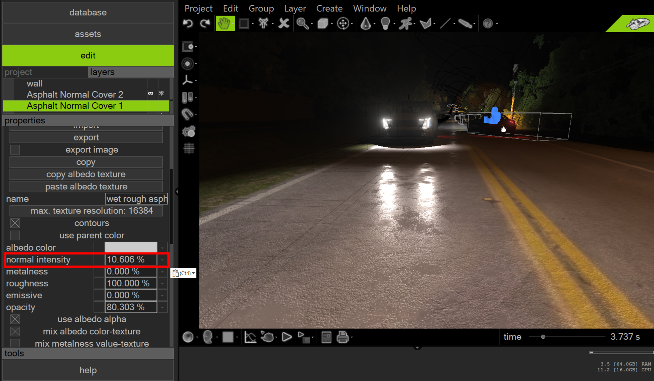
The “mix” toggles offer enhanced control, allowing you to use scale sliders to fine-tune the appearance of each channel. In the example below, we overlay a filled polyline on our road surface as seen in the orthomosaic imagery data. Next, we apply a wet road material to the filled polyline, but we activate “use albedo alpha” and “mix albedo color-texture”. This adjustment enables the use of the transparency slider in the “albedo color” drop-down menu to make the material’s albedo channel transparent, effectively utilizing only the other material channels. However, setting the normal channel to 100% results in an overly pronounced appearance of damage and wetness.
Adjusting the normal intensity slider downward enables us to leverage the material’s properties while affording us precise control over the road surface's final appearance.
This process is illustrated in the video below.
Note that materials can be superimposed and combined. For instance, two filled polylines with distinct materials can be overlaid, creating complex and unique material blends.
Experimenting with these various channel settings is crucial to fully understand their impact on surface appearance.
Exporting materials
Each material listed in the materials section can be exported using the “export” button. This action generates a proprietary .vcl material file, which can be conveniently reused in future projects by dragging and dropping it from the Windows File Explorer. To have Virtual CRASH generate a thumbnail preview of the material, ensure to enable the “export image” option.
Copy/Paste Functionality
You can copy materials from the material list of one object and paste into the material list of another object. This is demonstrated below.
Exporting albedo via copy
Materials feature both “copy albedo texture” and “paste albedo texture” buttons, enabling users to copy albedo images directly to the Windows clipboard. These images can then be pasted into any image editing software for modifications. After editing, the updated image can easily be pasted back into the material using the “paste albedo texture” button. This workflow is illustrated below.
© 2024 Virtual CRASH, LLC. All Rights Reserved