

Blog | Summer 2025 Software Update
Last updated: 7/13/2025

Just as summer temperatures are starting to rise, so is the excitement around our latest release. The Summer 2025 Software Update has arrived, bringing an expanded collection of new assets, refined interface updates, and enhanced features to help you work more efficiently and effectively. Best of all? It's completely FREE! No additional license fees or annual maintenances fees! Read on to learn more about this awesome update.
VC6 Updates
Automatically partition large orthomosaics images into tiles and .tfw files >
Suspension model performance improvement: Pre-load force solver >
New variables for dynamics info and on-screen dynamics info tool >
VC5 Update
VC6, VC5, and VC4 Updates
Upcoming in-person training classes


VC6 Updates
Automatically partition large orthomosaics images into tiles and .tfw files with the image to tiles tool

If you have large orthomosaic images which exceed your graphics card’s per-image display resolution, you may wish to partition your ortho into tiles first, before importing to preserve image quality. This single ortho vs. ortho tile import workflow is discussed in detail in this blog post (it’s also covered in great detail during our standard in-person training classes). Exporting orthomosaic tiles is easy enough in applications like Pix4Dmatic and Pix4Dmapper; however, in applications like the (generally) free photogrammetry application RealityScan (formerly RealityCapture), it can be a little more difficult.
If you use an app that does not export to tiles, or you have a case where a large orthomosaic lands on your desk, you’ll love the new Image to Tiles Tool. Our example image is shown below, opened in the free image editor GIMP. The image pixel size is 71.8k x 18.5k, which exceeds the per-image display capabilities of any graphics card.
To split this image into tiles using Virtual CRASH 6, simply deselect all objects (left-click into empty space) to reveal the project settings (learn more). Next, open Tools > “Image Tools”.
Next, you’ll need to decide if you want to reduce the image resolution before tiling. If your orthomosaic was created at a much higher resolution than warranted by the image quality itself (for example, flying a drone with a dirty lens at low altitude), then it may be sensible to reduce the image resolution to conserve GPU resources, provided you don’t lose resolving power as it relates to roadway evidence.
Next, select what pixel size you want to use per tile. This will depend on your graphics card, but you may also notice speed or performance differences as a function of tile size.
Next, left-click on “Image to Tiles”. The Windows File Explorer window will appear. Find the image you wish to tile. You’ll then see a progress box appear, as shown below.
Next, you’ll be asked if you want to import the new tiles.
Left-clicking “Yes” will trigger the standard importing procedure to begin.
As usual, the tiles are placed into a single group object.
Note: the Image to Tiles Tool automatically creates a folder based on your image name and the settings used. The tiles and corresponding TFW files (if generated) are automatically placed within this new folder.
If you wish to load and automatically align the point cloud, also made within the same photogrammetry project, there are two workflows to choose from.
Importing and aligning point cloud with tiles | Workflow 1
One option is to simply load the point cloud into the scene, copy the reference point (learn more) from one of the orthomosaic tiles and paste to the point cloud.
After pasting the reference point to the point cloud, press [F5] to ensure the full point cloud is above the x-y plane; otherwise, you may not be able to create a terrain mesh using all of the ground points due to some of your points being beneath the x-y plane.
Importing and aligning point cloud with tiles | Workflow 2
Alternatively, when asked if you want to load tiles after left-clicking “image to tiles”, left-click “No”.
Go to the folder where the tiles are placed, and put your point cloud and photogrammetry project’s main TFW file into this folder and use the multiple orthomosaic image tile import functionality (learn more).
Next, go to Project > Import, change the file type in the lower right corner to “tfw files”. Next, navigate to the tiles folder. Select all tfw files and press “Open”.

The import dialogue box will show the point cloud and all other loadable assets which have the correspondingly named TFW file included in the folder (this can be useful if you have divided up your point cloud into on-ground and off-ground points for example. Learn more >).
Note, with workflow 2, there is no need to press [F5] after the point cloud loads as its lower bounding box surface will automatically be aligned to the x-y plane.
Scenario without TFW file
If no TFW is found alongside the single orthomosaic, you will be notified.
If “Yes” is selected, the tile process will proceed. The final result cannot be automatically load into the scene since scale and position information provided by a TFW file will not be available; therefore, Virtual CRASH will simply open a File Explorer window to the final output.
Suspension model performance improvement: Pre-load force solver
Workflow 1 | For additional load via “pick leader” and/or “mass properties” menu options
This update resolves an issue that occurred when adding additional cargo weight or shifting the center of gravity on a trailer, which could cause the lead vehicle’s suspension to bottom out depending on the trailer’s total weight. Previously, the recommended workaround involved adjusting the suspension stiffness and/or modifying the lead vehicle’s mesh orientation to compensate for unwanted pitch (see this KB post for the older method).
As of the Summer 2025 Software Update, users can now simply go to the lead vehicle’s axles menu and enable the “automatic pre-load adjustment” toggle. This will automatically increase the lead vehicle’s suspension pre-load forces to compensate for the additional weight introduced by trailer joint coupling forces. The same option can also be enabled for the trailer.
This feature also works if front occupants, rear occupants, roof cargo, trunk cargo, and the add cargo weight options are used in the mass properties menu.
Workflow 2 | For additional load from independent rigid body objects, with or without joint coupling
Users can now automatically adjust suspension pre-load to compensate for added weight from independent rigid bodies, whether or not they are joint-coupled (via the joint options available under Create > Physics). Note: do not use this option without placing additional independent rigid body objects onto the vehicle to offset the additional suspension pre-load. In the example below, the car hauler carries four independent simulated vehicles. The added weight from these vehicles causes the hauler’s suspension to bottom out.
To use this feature, first enable “automatic pre-load adjustment” for the vehicle whose suspension needs adjustment. Then, go to the mass properties menu and click the “add” button to create an additional cargo mass. For that mass, enable the “for suspension pre-load adjustment” option. Next, switch the cargo selection type, activate “Select and Move” [F2], and enable the gizmo (press [1] at the top of the keyboard). Move the cargo mass icon to approximately match the position of the independent rigid body you want to use for pre-load adjustment. Note: For each entry in the additional cargo mass list labeled “(pre-load adjustor)”, the specified mass is not added to the vehicle’s total system mass. Instead, it is used only to increase suspension pre-load.
In the example below, a separate additional cargo mass element is created for each independent car on the hauler. Notice the hauler’s suspension no longer bottoms out.

Note: Only the static pre-load forces are adjusted when “automatic pre-load adjustment” is enabled. Once the simulation begins, the pre-load forces remain fixed and do not change dynamically. Additionally, using Workflow 2 above, independent rigid bodies can also be manually joint-coupled to simulate tiedowns (learn more).
Workflow 2 also works in cases where converted multibodies are manually joint-coupled to vehicle objects (learn more).
Advanced Link Tool
Point cloud linking was first introduced in the Spring 2022 Software Update (learn more). This feature was generalized with the release of the Link Tool, introduced in the Winter 2022 Software Update (learn more). The new Advanced Link Tool is the next advancement in linking functionality! With the Advanced Link Tool, users can now easily re-attach existing lights, cameras, dynamics info boxes, (passive) 3D mesh geometries, and 2D CAD elements to rigid body objects or to kinematics objects. This eliminates a long-time challenge of needing to first attach these objects to kinematics instances.
An example is shown below, where lights, a camera, a dynamics info box, and a mesh representing the driver are first attached to our simulated truck. Afterward, the Kinematics Tool is used to add additional motion before time = 0. However, you’ll notice the attached objects do not attach to the kinematics object.
The prior solution was to start over from the beginning and recreate lights and cameras, attaching them to kinematics. As of the Summer 2025 Software Update, this is no longer necessary! With the Advanced Link Tool, simply select the (unfrozen) linkable object(s), go to the “misc” menu, left-click on “link”, then left-click on the object in 3D space you wish to link to. These three steps are shown below.
Note: lights, cameras, 2D CAD elements, and passive (non-rigid body) mesh geometries can be linked to rigid body meshes, non-rigid body meshes, 2D CAD elements, and kinematics objects. Dynamics info objects, however, can only be linked to rigid bodies and kinematics objects. Once you left-click on the target object, all previously selected objects will be transferred to it at the exact same local position and orientation they had relative to the original object.
Note: When linking an object that does not yet have a parent, it will be attached at the point where you left-click on the intended parent. The object will adopt the same yaw, pitch, and roll values, transformed into the parent’s local frame. When re-linking an object that already has a parent to a new parent, it will retain the same relative position and orientation within the new parent’s frame as it had in the original parent’s frame.
Un-Link
To unlink an object, simply left-click “Link” and then left-click on an empty region of your scene.
Linking a Camera’s Target or Creating a New Camera Target
A camera can be made to look directly toward an object after the camera’s initial creation by first selecting the unfrozen camera, then left-clicking on misc > “look at”, and finally left-clicking on an unfrozen object of interest in the workspace. If no target already exists for the camera object, one will be created and placed on the selected object. If a target does exist, it will be moved to the selected object. This is very useful, as you no longer need to create a new camera object simply to place a camera target into the scene.
Note: if you wish to unlink or remove a camera target, simply delete the target object in the project list or left-click “look at” and left-click in an empty space within the scene.
Advanced lights, camera, and passive mesh object position and orientation control via time-series data
Position and orientation control by time-series, first introduced in the data animation control tool released in the Spring 2023 Software Update (learn more) and then enhanced in the Summer 2024 Software Update (learn more), has now been extended to work with lights, cameras, camera targets, and non-rigid body meshes! Note: we recommend reviewing these two posts before using this new feature. There’s no longer a need to create a parent simulated rigid body to advanced camera tracking. Simply go directly to the object’s tools > “animation menu”, select your data format, and either paste directly from the Windows clipboard or import from a text file.
In the example below, the simulated truck’s dynamics report data was copied to the Windows clipboard (ctrl+c) and pasted into its animation data menu using “paste text data”. Once this is done, the camera’s initial position can be modified as needed, but its trajectory shape and orientation will be determined by the pasted data. Note: selecting two or more objects at once and pasting data will force them both to move together even as you adjust their initial positions.
Once the time-series data is loaded, you can access it by going to the object’s x, y, z, yaw, pitch, and roll dropdown menus (empty box to the left of the given input field) and selecting “edit.” Notice a new type of diagram input option is available: “data” (be very careful! Left-clicking “data” rather than “edit” will delete your loaded input data). Note: you can learn more about the diagram tool at this post. As always, the diagram inputs can be interactively modified using the white dot control grips. Modifying “offset y” will change the initial value of the selected input variable. Modifying “offset x” will shift the data forward or backward relative to simulation time. Note: for yaw, pitch, and roll, in the “output” menu, you will typically want to leave the “spherical linear interpolation” toggle in its default enabled state.

New variables for dynamics info and on-screen dynamics info tool
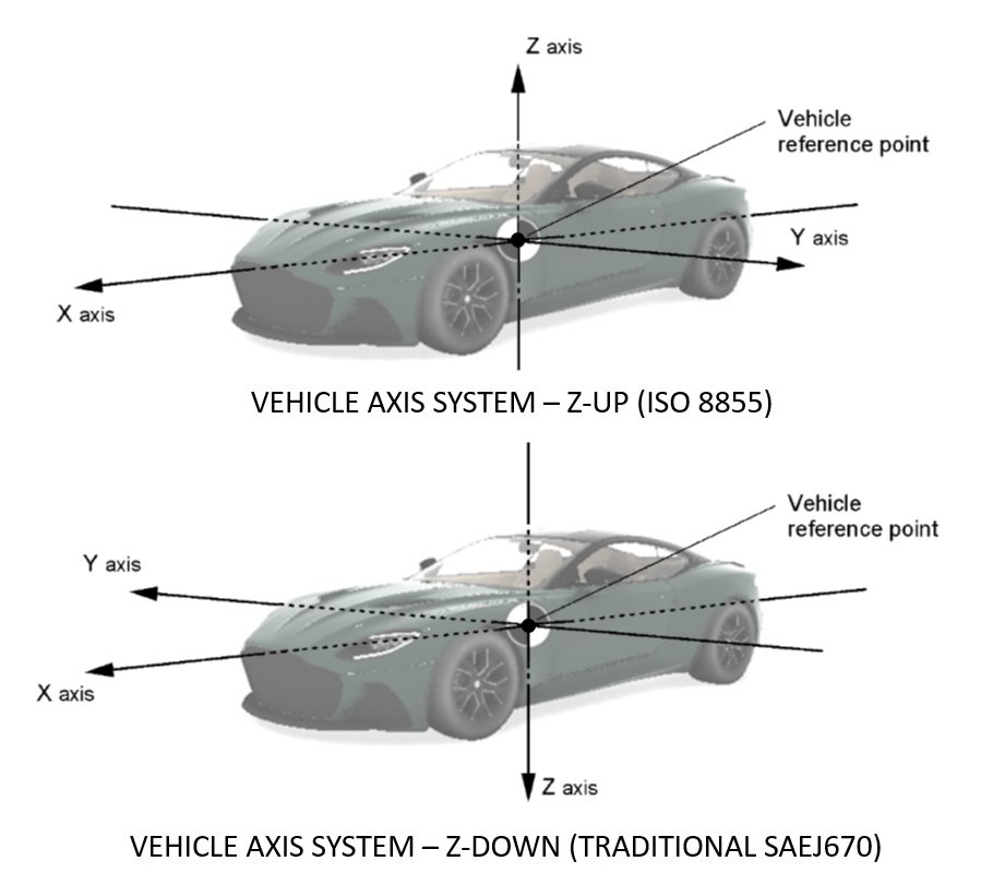
Recall from the Virtual CRASH User’s Guide, the coordinate system is right-handed with z-up (see ISO 8855). The Dynamics Info Tool can be used to display various parameters to the screen. You can find the list of parameters at this post. With the Summer 2025 Software Update, we’re adding to this list some new parameters.
New: \(\Delta\)V components and PDOF (traditional SAE J670 orientation: right-handed with z-down):
{dvx_sae} = {dvx}: x-component of CG Delta-V vector (traditional SAE J670)
{dvy_sae} = -1 * {dvy}: y-component of CG Delta-V vector (traditional SAE J670)
{dvz_sae} = -1 * {dvz}: z-component of CG Delta-V vector (traditional SAE J670)
{dvni_sae} = -1*{dvni}: Angle between x-y projection of CG Delta-V vector and x-axis (azimuthal angle) (deg) (traditional SAE J670)
{dvnz_sae} = -1*{dvnz}: Angle between x-y projected CG Delta-V vector component and CG velocity vector itself (polar angle) (deg) (traditional SAE J670)
{pdof_sae} = -1*{dvni(local)} +180 deg: Alternative definition of angle between x-y projection of CG Delta-V vector and x-axis (azimuthal angle) (deg) (traditional SAE J670). Also see discussion in this KB post.
Note: If you want to display components and angles relative to vehicle frame (not global frame), be sure that “use global space” is disabled. This will be disabled by default as of the Summer 2025 Software Update. {pdof_sae} is only defined in local space and so is not affected by toggle.
Note, the Dynamics Info Tool can also be directly attached to an Accelerometer Tool (learn more) to estimate Delta-V vector quantities at any point within the vehicle’s frame.
Auto-ees / user contact ees objects
Auto-ees and user contact ees will now show “impulse pdof (local, sae)” under the “object 1” and “object 2” menus.
Recall the auto-ees object found in the project menu is a data container which contains the list of all automatically generated Kudlich-Slibar impulse exchanges, whereas a user-created EES impulse object is either generated using auto-ees > selection > “create user contact” or manually by using Create > Physics > Create EES Impulse. Each individual impulse exchange will have its own associated parameters listed in the “object 1” and “object 2” menus. For a given impulse exchange, you will find:
Impulse ni: Angle between global x-y plane projection of CG Delta-V vector and global x-axis (azimuthal angle) (deg)
Impulse nz: Angle between global x-y plane projected CG Delta-V vector component and CG velocity vector itself (polar angle) (deg)
Impulse ni (local): Angle between local x-y plane projection of CG Delta-V vector and local x-axis (azimuthal angle) (deg)
Impulse nz (local): Angle between local x-y plane projected CG Delta-V vector component and CG velocity vector itself (polar angle) (deg)
Impulse pdof (local, sae): Alternative definition of angle between local x-y plane projection of CG Delta-V vector and x-axis (azimuthal angle) (deg) (traditional SAE J670). Also see discussion: https://www.vcrashusa.com/kb-vc3-article12
Remember, the values listed in the auto-ees and ees object “contact”, “object 1”, and “object 2” menus are per individual impulse exchange. This differs from the cumulative calculations performed by the Dynamics Info Tool, which account for multiple impulse exchanges over a user-defined window of time. To remind users of this difference between the cumulative effect of multiple impulse exchanges versus a single individual impulse exchange, “delta v” found in the “object 1” and “object 2” menus has been relabeled to “delta v (impulse / mass)”. That is, this delta v value is simply the impulse vector’s magnitude divided by the object mass. This may or may not be equal to the full collision event Delta-V for the given object, and will depend on other potential impulse exchanges, tire forces, trailer and other joint coupling forces, etc.
Other interface improvements
Forward facing camera
With the Summer 2025 Software Update, begin by left-clicking Create > extended Primitives 3D > Camera. Then, press and hold shift+left-click, and drag your cursor to the object you’d like to attach the camera to. Release the mouse button. Move your mouse up or down to adjust the camera’s height (z-axis), then left-click again to place it. Right-click to exit the camera command. The camera will now be linked to the parent object and oriented to face forward.
New hotkeys: you can now use “W” to switch to “Axis World “ mode and “L” to switch to “Axis Local” mode.
Update related to Cloning: when cloning objects (learn more), “use copy” will now be the default selection.
Update related to Dynamics Info and On-Screen Dynamics Info Tools: (also discussed above) “use global space” is now DISABLED by default. Recall, when this is disabled, various vector angles and vector components will be displayed relative to the object’s local frame.
Update related to loading background images and videos onto camera objects: you can now drag and drop your image or video icon directly from Windows File Explorer onto a camera object to load a background, rather than going to background > file.
Open Windows File Explorer, find your image or video file. Hold+left-click and drag the file icon onto your (unfrozen) camera object.
You’ll be asked if you want to replace the current background. Left-click “Yes”.
You should then see the image or video loaded onto the camera background. As usual, the background can be removed by left-clicking the “x” to the right of the background > file button.
Additional improvements
When in video viewer mode for object tracking > manual track point, use ctrl + shift + scroll wheel to advance video forward frame by frame.
Fixed issue related to save-file prompt which is automatically triggered with tools > animation > create.
Fixed real-time render issue which occasionally caused flashing/blinking sections of point cloud data.
VC5 Update
Advanced Data Animation Control with GPS Support
The DAC can now take (longitude, latitude, altitude) time-series data. In the example shown below, GPS data was obtained from a Berla report. This data was imported into Excel and put into (time, latitude, longitude) format. “data format: user” was used to define these three columns of data. Once the data was copied from the spreadsheet, “paste text data” was used to import the data to the DAC. The DAC was linked to a parent rigid body cylinder object meant to represent the vehicle CG location. Note: The illustrations below were created in Virtual CRASH 6 and take advantage of the automatic alignment of GPS-related data with Google Maps imagery.
To complete our visual of our vehicle’s path implied by GPS, we simple enable show interposition steps for our CG marker. We can view our marker moving along the trajectory in real time by pressing the play button.
New Assets
The assets below have been added to VC6, VC5, and VC4:
For VC6:
assets > other 3d > mannequin: New linkable meshes - Child Bicycle Rider (Boy), Child Scooter Rider (Boy), Moto Rider CBR250 (Man)
assets > other 3d > miscellaneous > Single Street Light 3
assets > other 3d > miscellaneous > Full Face Helmet
assets > other 3d > miscellaneous > Glasses 2
assets > other 3d > miscellaneous > Hair Style 1
assets > other 3d > miscellaneous > Child Scooter
assets > other 3d > tree > Tree 6
assets > textures > miscellaneous > Scalebar. This can be used as an albedo channel for a box object to make a 3D scalebar. Just drop the image into your scene, go to the image’s material menu, select the material, and left-click copy. Next, create a 3D box object. Go to the box object’s material menu and left-click paste. Press [F3], adjust box control grips as needed to measure the length of interest. Read off box dimensions in its misc menu. The control grips can be made to snap [Alt+s].
assets > textures > miscellaneous > Visible zone projection map. This can be used as a light projection map for line of sight studies (see video below). Note: for lights set to misc > “type: spot”, a projection map can be loaded either using projection > file, or by dragging and dropping the image onto the light object in the 3D workspace (learn more). See image to the right for other useful settings when using spotlights for this purpose.
For VC5 and VC4:
These vehicles have been added to the assets browser:
Freightliner Cascadia XT (2007)
Peterbilt Box Truck (2007)
