

Blog | Spring 2022 Software Update
The Spring 2022 Software Update has arrived. This FREE software update brings new surprises for users of Virtual CRASH 5, 4, and 3! Read below to learn more about these awesome updates! As usual, these updates come to you FREE of charge - Virtual CRASH users pay no annual “maintenance” or update fees.

Point Cloud Linking | VC5
Linking point clouds to rigid body objects is now easier than ever with the new “Link” option. This makes connecting vehicle scans to simulated vehicle objects as simple as pressing a button. You no longer need to use the grouped object workflow. See example videos below.
In the video below, we show examples of linked vehicle scans created with Eugene Liscio’s Recon-3D app.
Start by placing your point cloud in the scene with your simulated object. Here we have our point cloud vehicle next to our simulated vehicle. You can find scanned vehicle models such as the one shown below at Lightpoint Data.
Go to the point cloud’s “misc” menu in the left-side control panel. Left-click “link”. Finally, hover your mouse cursor over the simulated object you wish to link to. The object will turn light-blue to indicate that it will be selected (make sure the simulated object is not frozen). Finally, left-click on the simulated object to link the point cloud to the simulated object.
Now you can reposition your point cloud relative to the simulated object and the point cloud will translate and rotate automatically as the simulated object moves through the scene. The point cloud size will have no effect on the size attributes of the simulated object. This will work for simulated motion, animated motion, momentum solver, and kinematics! Note, when using kinematics, link the point cloud to the kinematics object rather than the rigid body object (same workflow as with lights and cameras).
New Hide Body Option
If you wish to hide the simulated object from view, you can use the the new “hide body” toggle in the object’s “misc” menu. For simulated vehicle objects, this will hide the mesh from view, but not the wheels.
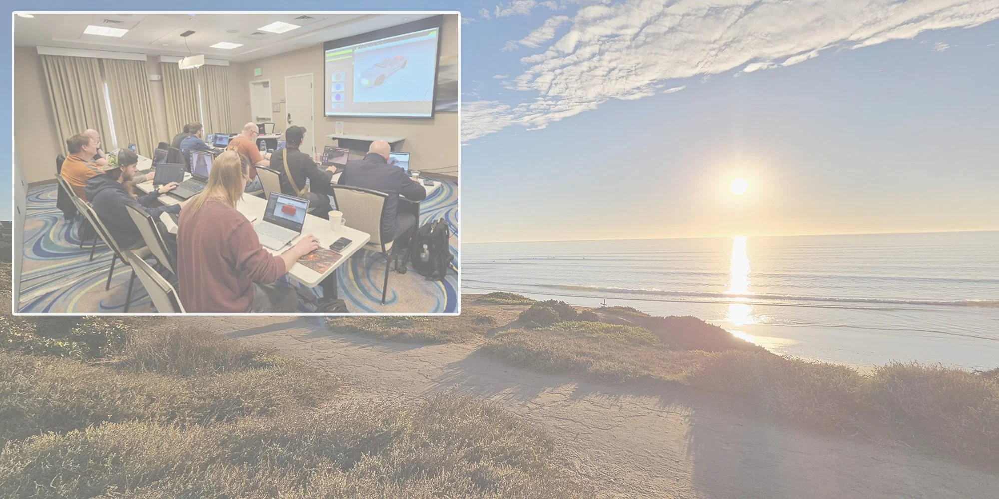
Upcoming In-Class Training Opportunities
The Print Template Tool | VC6 | VC5 | VC4 | VC3 | VCPS
With the Print Template Tool, it’s now easier than ever to create scale diagrams with a standardized format that’s best for your organization. The Print Template Tool is designed to make it easier for you to create physical scale diagrams from your Virtual CRASH project.
Recommended Workflow
First, in a blank project, go to Create > Helpers 2D > Print Template. Left-click “Print Template” and left-click in the project. As usual, right-click to terminate the command.
Now you’ll see the Print Template Tool in the workspace.
The red outline represents the boundary of the physical paper on which the diagram will be printed. The paper size can be modified using the “size” dropdown menu in the “paper” menu. Use the “landscape” toggle to switch between portrait and landscape. The diagram’s scale can be specified using the “scale” dropdown menu. Use the “left”, “top”, “right”, “bottom” input fields in the “margins” menu to set the margins of the diagram.
Switch to “Select, Move and Manipulate” cursor control type, then select “Guidelines” in the object selection type dropdown.
Left-click on one of the “+” symbols, hold, and drag your mouse left or right (or up and down), to create a guideline. Each guideline will be shown in the list in the “guideline” menu in the left-side control panel. As shown above, using the upper “+” symbol defines a guideline from the upper edge of the page. This is also indicated by the “from: top” option in the “guideline” menu. The distance from the upper page edge and the guideline is controlled by the “distance” value (note, the distance is the physical distance on the page relative to the margin). This can be specified by keyboard entry or by using the control grip. Note, after the guideline is created, you can modify its position interactively by left-clicking on the red guideline, holding, and dragging the mouse cursor (you must be in “Guidelines” mouse cursor control type).
Here we’ve created six guidelines to create various zones in our print template. Each zone, defined by the page boundary and the various guidelines, can have a different element inserted into it. Note, we’ve placed the Print Template Tool at position-local (x,y) = (0,0) and modified our grid lines to make it easier to adjust the layout.
With the Print Template Tool actively selected, switch to “Elements” selection type and open the “element” menu in the left-side control panel. “Left-click, hold, the “+” symbol that appears when you hover over the intersection point made between two guidelines (or page boundary and guideline). Next, drag to diagonally to a second intersection point made by two guidelines (or page boundary and guideline). The rectangular area defined by these two opposite corner points defines a zone within which you can place an “element” (text, image, north arrow, or scale indicator).
This zone will be highlighted red once created, and you’ll see its name appear in the “element” menu.
Scrolling down the left-side control panel, you’ll find additional options for the element’s zone. For example, the guideline indices, which specify which guidelines are being used to define the element’s zone are specified (note, the index counts from left to right for left and right boundaries and up to down for the top and bottom boundaries). Each zone can have additional padding specified and well as a border. Note, when multiple zones are defined, each one can be selected interactively by left-clicking inside the given zone while in “Elements” selection type.
The type of element to appear in the zone can by specified by the “type” dropdown. Here we specify an image to be used for element 1. In this case, an image element can be loaded using either the “texture” button or by dragging and dropping an image into the image element’s zone. Note, if the “background” toggle is enabled, the zone will have a white fill color behind the element; otherwise, the background will be transparent.
Next, we insert our second element, which will be “type:compass”. This type is also an image format, but the image will always stay aligned with the global y-axis, even if rotation-local yaw of the Print Template Tool is non-zero. In this case, our north arrow image came from the gallery browser (gallery > other 2d > north arrows). Simply drag and drop the north arrow graphic into its zone.
Next, we insert additional guidelines in order to define a small zone in the bottom right to inject our third element of type scale. Note, elements with “type: scale” have text attributes, such as font, bold, italic, and size, which can be modified as needed.
Next, we insert another guideline and text element. Elements of type text have a “text” input field, where you can type any text you wish. Here we simply add “Scale” to appear next to the scale element. Remember, you can switch back to “guideline” selection type and dynamically modify the placement of each guideline as needed. The corresponding elements within each zone will adjust in size and placement as you modify your guidelines.
Finally, we place an additional text element at the center-bottom of the page, and we place another large element across the full diagram in order to define a black border around the full diagram.
Left-click on the Print Template Tool in the left-side control panel. Next, go to the print icon and select “Print Preview” to see a preview of the template.
Finally, we save this template as a .vc6, .vc5, .vc4, .vc3, or .vcps file.
Next, open your subject case project. Go to Project > Import and open your print template Virtual CRASH file (you can also simply drag and drop the file from the Windows file explorer).
Here we see the Print Template Tool in our scene. Note, the yaw value of the Print Template’s rotation-local menu is set to the yaw value of the text objects and scale bar in our scene. This ensures that our text boxes are printed along a horizontal line within our scale diagram.
Once imported into the scene, you are free to make whatever additional changes you wish. To preview the resulting scale diagram, first ensure that the Print Template Tool is selected in the project menu (or layers menu). Next, go to the Print menu, and select “Print Preview”. When simply previewing the diagram layout, it is recommended to use “Render – Current” to avoid ray tracing in Direct Light or Skylight, which can take more time to complete.
Note, the Print Template Tool always renders from the top-down orthographic view no matter what the view setting is in your interactive workspace window.
Once you are satisfied with the layout of your diagram, it is recommended to create the final version in Direct Light or Skylight render mode for the highest quality. You can increase the quality using the “Print DPI” setting. Note, by lowering “Print Preview DPI”, you can speed up the production of print previews in Current, Direct Light, and Skylight mode.
Here we see a Print Preview in Skylight at the maximum “Print Preview DPI” setting (note 0 = maximum value).
To print without previewing, select “Print”. When using the Print button, do not forget to ensure the Print Template object is selected in the project or layers menu, otherwise the printout will not be of the template’s view.
Here we see our final diagram in pdf format.
Note, you can clone a Print Template like any other object. This allows you to create multiple diagrams with a standardized format for many different areas within your project.
Human Animation Tool | VC5
The motion clip library of the Human Animation Tool has been expanded and now includes categories “in motion (neutral)”, “standing stationary (neutral)”, and “falling motion”.
Below is a trip and fall visualization created using some of the new motion clips in this update.
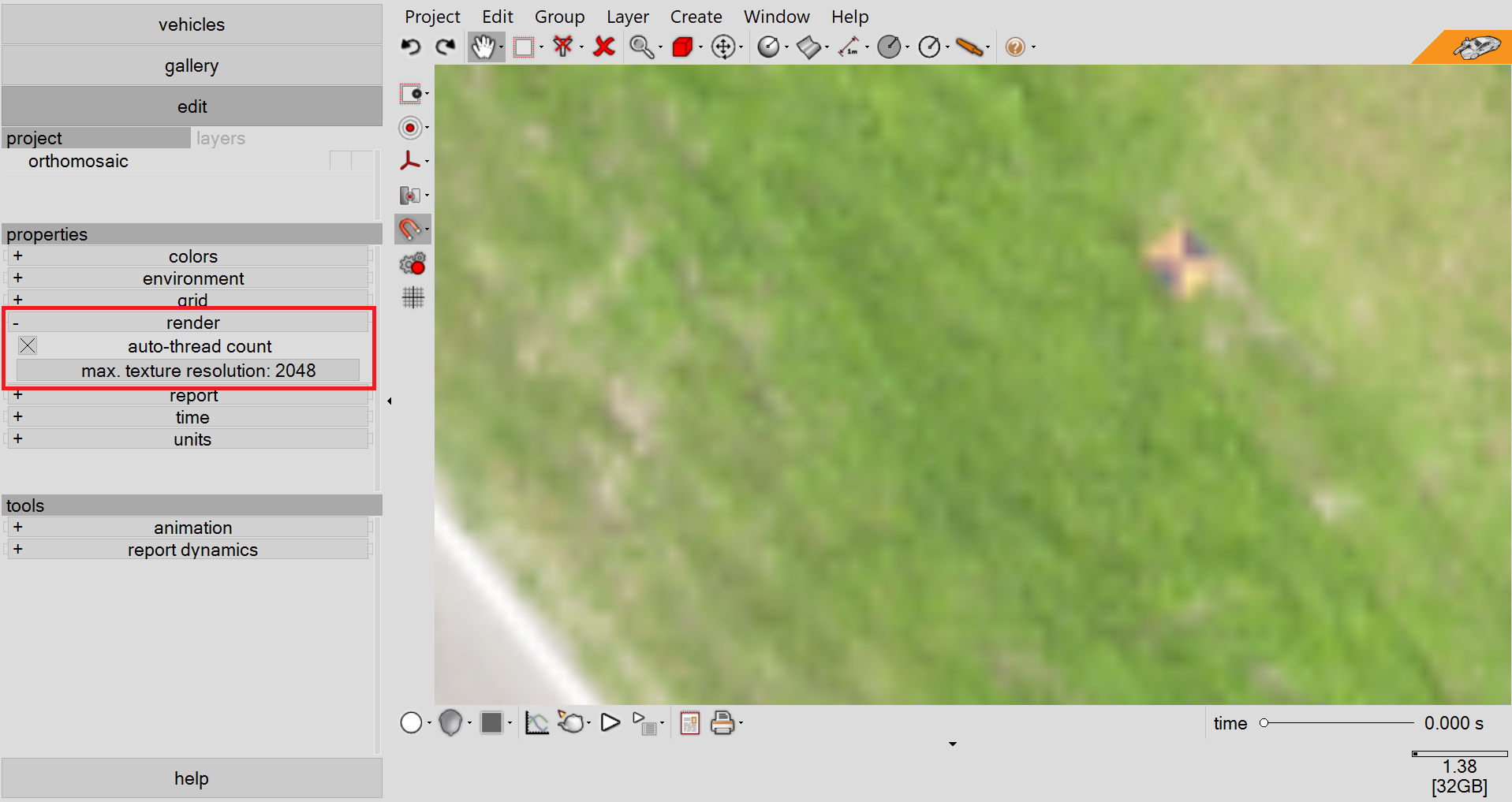
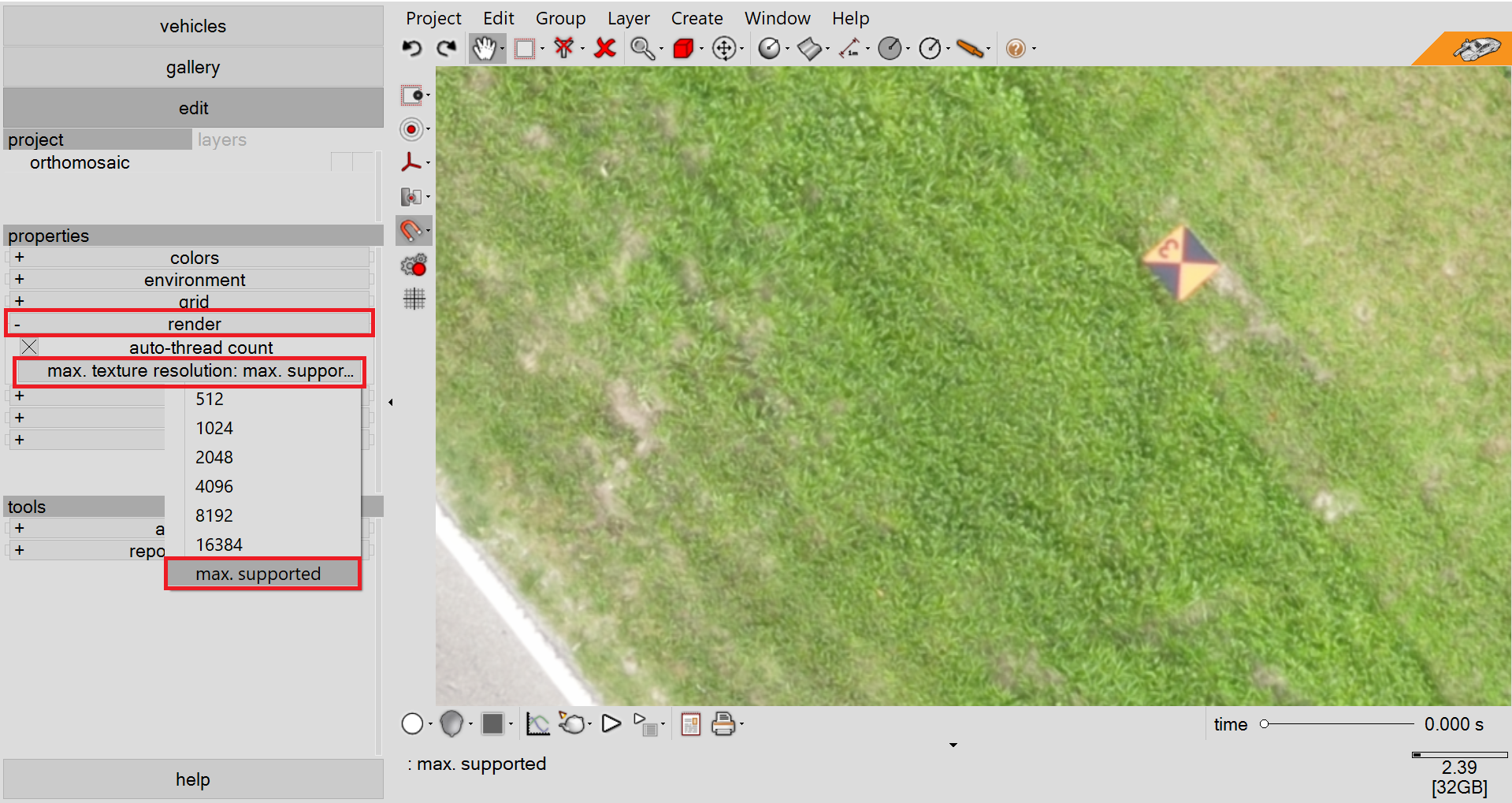
Maximum Texture Resolutions Improved | VC5
VC5 users can now take advantage of the new project setting “max. texture resolution”. This will control the maximum image and texture sizes loaded into your graphics card memory. For each image or texture that is imported into the project, if the image or texture resolution is larger than the selected size, its resolution will be decreased such that it satisfies the setting.
To set this property, go to the “properties” menu in the left-side control panel (you can access the project properties menu by ensuring no objects are active in the project menu or layers menu – remember right-click will deselect and object). Next, open the “render” menu. Select the desired maximum texture resolution to be used for the project using the “max. texture resolution” dropdown menu. If you have already placed images or textures into the project, changing “max. texture resolution” will trigger Virtual CRASH to reload all images with the new setting applied (for larger projects, this can take time to complete). Virtual CRASH will check for all images and textures in the relative and global paths. If a given images or texture cannot be found, Virtual CRASH will skip the reloading process for that file. Note “max supported” will be based on your specific graphics card. For large scenes, where a 3rd party photogrammetry application was used, it is recommended to use the Smart Alignment Tool with image tiles if possible, to preserve maximum image quality across your entire scene.
Improvements to Easy Surface Builder | VC5 | VC4
The Easy Surface Builder has been improved for Virtual CRASH 5 and Virtual CRASH 4. A list of improvements can be found below:
The default fit function is now “average” rather than “max”.
You can now increase the texture map size of the resulting mesh geometry up to the maximum supported by your graphics card.
The maximum allowed length segs and width segs has been increased. For VC5, you can increase both length segs and width segs as needed, but such that the total polygon count will not exceed 1 million (that is, “length segs” x “width segs” will not exceed 500,000). For VC4, the total polygon count will not exceed 500,000 (that is, “length segs” x “width segs” will not exceed 250,000)
The maximum “cap radius” value is now 300 (note you will need to type in values greater than 30).
The maximum “texture cap radius” value is now 100 (note you will need to type in values greater than 30).
The maximum “smooth” value is now 300 (note, you will need to type in values greater than 30).
Improvements Terrain Mesh Optimization Feature | VC5 | VC4
The “optimization” feature for terrain meshes has been improved. Users can now specify more length segments and width segments, such that “length segs” x “width segs” will not exceed 90,000 grid cells.
Steering Angle Display | On-Screen Dynamics Info | Dynamics Info | VC5 | VC4
On-Screen Dynamics Info and Dynamics Info can now display a vehicle’s steering angle. Simply use the variable {sa} in the text box. Remember, using {sa:<N>} will select the numerical precision of the displayed value, where <N> is the number of decimal places to be displayed.
Point Array Improvements | VC5 | VC4
Point Arrays now have a “show points” toggle in the “misc” menu. This allows the user to control the visibility of points even if the “triangulate” (Total Station / RTK GPS Surface Builder) option is enabled.

Snap-to and/or Show Object Pivot is Now Available | VC5 | VC4 | VC3
In the Snaps menu (magnet icon), you will now find the “Pivot” toggle. With this, you can snap polylines, dimension lines, Path Animation Tool, and other items to the pivots of any object. Remember, the pivot point is the center of gravity (CG) location for a rigid body.
In this example, we snap our polyline to the CG of our simulated vehicle to draw a trajectory line. Simply move the time slider to visualize different positions of your simulated objects and snap the polyline to the CG position.
Every object now has a “show pivot” toggle in the “misc” menu. When you enable this object, a marker will be displayed at the object’s pivot point. For rigid body objects, this marker will indicate the object’s center of gravity (CG).
Pivot points can be snapped to and displayed at the same time.

Reference Point Copy/Paste Button | Mesh Reference Point Attribute | VC5 | VC4
Mesh objects now have Reference Points. This makes aligning meshes from 3rd-party applications even easier. Additionally, the “reference point” menu now has copy and paste buttons. So, if you have multiple assets (for example, point clouds that were divided into multiple parts, point array data, meshes, etc) defined in a common coordinate system, simply copy the reference point from the anchor asset, and press the paste the reference point for the other assets to be aligned with the anchor.
For example, here we have a mesh imported into our scene, created with PhotoModeler. The mesh is defined with respect to the same coordinate system as the point cloud.
We can open the “reference point” menu for our point cloud, which we’ll use as our anchor.
Next, we select our mesh, and left-click the “paste” button in its “reference point” menu.
Now the mesh is aligned to the point cloud.
In the example below, we align two point clouds using the reference point copy and paste buttons.
Here we have aligned the tree points (with larger display and render size) with the original point cloud to provide the appearance of dense foliage.
Active Suspension when Stop Simulation Used | VC5 | VC4 | VC3
When creating scale diagrams using simulated vehicle objects, it’s common to disable physics (Create > Physics > Stop Simulation) so that all simulated objects become static. Now when physics is disabled, suspension effects for simulated vehicle objects will remain active. With this improvement, users no longer need to “toggle” physics on and off to extend wheels to contact the terrain. This feature is illustrated in the video below.
Additional Snaps Improvements | VC5 | VC4
When Snap to Point Array is enabled, you will now be able to snap to frozen objects, including Point Arrays and Point Clouds. This will, for example, allow the user to position a Point Array, freeze it to prevent accidentally moving it, yet snap CAD elements to it.

Axes Tool | VC5 | VC4 | VC3
The Axes Tool will default to spacing = 1.0 ft if the project distance units are set to feet (“metric: feet” in the “units” menu). If meters are used, the default spacing = 0.1 m.
Vertices Clean Up Tool | VC5 | VC4 | VC3
You can now use the “remove isolated vertices” tool in an object’s “vertices” menu to automatically delete vertices after deleting polygons. In the example below, we use this feature to remove vertices after we delete the mesh wheels and antenna from our imported vehicle object. Remember, a rigid body’s size attributes are measured relative to vertices, so it is important to ensure unwanted vertices are removed.
Here we switch to “Elements” selection type (Shift-E) to select the wheel and antenna polygons.
Next, we switch to “Vertices” selection type (Shift-V) to reveal the mesh’s vertices. The “vertices” menu in the left-side control panel is only visible when the “Vertices” selection type is enabled.
Finally, we open the “vertices” menu and left-click on “remove isolated vertices” to remove vertices associated with the deleted polygons.
Select, Move and Align | VC5 | VC4
The “Select, Move and Align” tool will now remain visible over 3D shapes such as point clouds. This makes it easier to manipulate images or other objects which sit underneath 3D objects. In the example below, we see the “Select, Move and Align” control grips for an image in “scaled image” mode. This orthomosaic image is being scaled, rotated, and aligned using the reference point cloud hovering above it. The control grips remain visible to make this process easier.
Improvement to Force Tool | VC5
The Force Tool now has the “use global space” toggle. This will lock the force vector’s orientation in global space rather than local space. When the toggle is disabled, the force vector’s orientation will be locked in the object’s local space.

Shadow Maps Option Disabled by Default | VC5 | VC4
“use shadow maps” will now be disabled by default in the “animation” menu.

Gallery Updates | VC5 | VC4
Multibodies can now be created from the gallery. Left-click “multibody” then drag and drop from the icons.
Point Cloud Section Tool Fix | VC5
For the “section” point cloud tool, “select max. memory: unlimited” will now load all points into memory.
Opening 3DS Files | VC5
Fixed issue with opening certain 3DS files.
Groups | VC5 | VC4 | VC3
Now hiding or freezing the group object folder icon will hide or freeze all elements no matter if the folder icon is open or closed.