

Blog | The Image and Video Rectifier Tool
Last updated: July 3, 2024
Virtual CRASH offers users many powerful features to help analyze accident cases. One gem of a feature that’s often overlooked is the image rectifier tool. This tool works by scaling and rectifying a planar region of a scene that is visible within a photograph or video. When using this tool, be sure the witness marks you’re attempting to orthorectify are contained within the identified planar region. The tool itself is essentially selecting a specific area within the planar region to use to set the image scale. You can easily create your own test cases using Virtual CRASH, such as the one shown below. Videos are specifically discussed at the end of the post.

In this post, we’ll review the functionality of the image rectifier tool and give a proof of concept using data from a staged collision. A video of the workflow can be found at the bottom of this post. You can also learn about the image rectifier tool using the Virtual Tutor by going to help > images > rectified.
Suppose you’re asked to review an accident case that occurred a few years ago, and suppose you’re only given a couple of photographs taken from a perspective view by one of the first responders or crash investigators. If these photographs depicted some visible evidence, such as tire marks, it could be advantageous to be able to position the tire marks within your Virtual CRASH project environment. This is where the image rectifier tool comes in.
Here we have a photograph taken after crash test #3 at the 2018 IPTM Symposium on Traffic Safety.
In the photograph above we see a mark created by the passenger side rear tire (the mark was made by a combination of the tire and a chain that was used to lock the rear wheels during the crash test). Using the image rectifier tool, we’ll try to estimate the position of this tire mark in space by using the image rectifier tool. Below is a video of the crash.
Let’s suppose we conduct a scene inspection a couple of years after the subject accident. We expect the witness marks no longer exist, but other features in the environment may remain, such as the road striping. In our test case, a year after the 2018 crash test, we returned to the scene for the 2019 IPTM Symposium, where other tests were done in the same parking lot. This gave us an opportunity to create a new point cloud and orthomosaic of the scene without the evidence from 2018 test #3.
During the 2019 Symposium, a DJI Mavic 2 Pro was flown over the scene and Pix4D was used to process the drone photographs, resulting in an orthomosaic, point cloud, and tfw file. Using the Smart Alignment Tool, we can load this data and ground control points into Virtual CRASH. The 2019 scene data is imported into the scene automatically aligned, and from this we can obtain our reference measurements.
Next, we drag and drop in our perspective image of interest. Right-click on the image to bring up the command menu. Left-click once on “use” to change the image to “rectified image”.
Next, use the object selection type to choose “Rectify”. You’ll see the rectify tool appear over the photograph. Align the four corners of the rectify tool to visible features on the road surface. You’ll need to select points such that the distances between them can be determined somehow. In our test case, we’re using the point cloud created a year later to measure the distances of the parking space stripes. In this case, the road is the planar surface on which our markings are contained. We’re using the image rectifier tool to identify the planar surface and set its scale.
Legacy Workflow | Using Measured Distances
Next, we measure our reference distances from our 2019 point cloud data and enter them into the left-side control panel. Interestingly, we can actually see the mark still visible a year later in our reference 2019 orthomosaic of the scene. Note, the preferred workflow is presented below.
Next, we use the “create region” tool to crop our image, keeping only the planar region of interest from our subject photograph.
Now switch back to the “Object” selection type. You should see the cropped, scaled, and rectified image.
Next, we superimposed our rectified subject photograph onto our 2019 reference orthomosaic. Here we align our images using the parking space stripes.
Next, we use the Easy Surface Builder to create our terrain mesh from point cloud data. With “receive projection” enabled, we now have our tire mark from the subject photograph positioned within our 3D environment.
To check our results, we superimpose our orthomosaic image of the scene from 2018 and compare it to the result from the rectified subject image. Below we see that the tire mark shown in the rectified image comes within a fraction of a tire width from the mark depicted in our 2018 orthomosaic created by Pix4D.
The workflow is shown in the video below.
Preferred Workflow | Select, Move & Align Tool
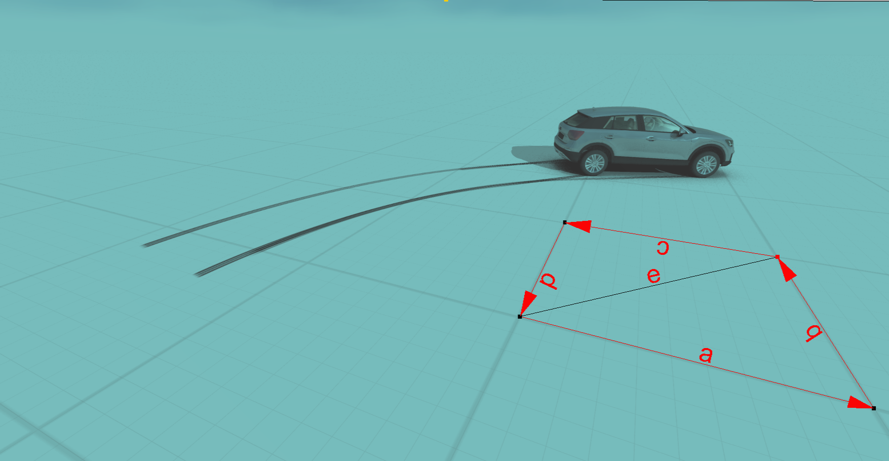
An alternative to manually measuring the a, b, c, d, and e lengths is to take advantage of the "Select, Move & Align" cursor control. This method is significantly faster.
First, switch to the Rectify [Shift+R] and align the black control grips to the points of interest in the image.
Once this is done, switch back to Object selection type [Shift+O]. Next, left-click "Select, Move & Align".
Once in "Select, Move & Align" cursor control, you should notice when hovering your cursor over the yellow control grips, a secondary translation control grip pops up. You can use the secondary control grip to move the yellow grip relative to the image as needed.
Once you are satisfied with the positioning of the yellow grips, hold + left-click and reposition each yellow dot control tip such that they are sitting on top of the corresponding points of interest within the scene. Once again, here we use the inside corner of the rectangle formed by the parking lot stripes. You may find it helpful to set the image to be semi-transparent for this process, so you can see the scene data underneath the image itself.
Repeat this process for all four yellow control grips. As you fine-tune the position of these control grips, adjust the image transparency to evaluate the quality of the fit.
Using the "Select, Move & Align" cursor control grips, the a, b, c, d, and e measurements are automatically estimated, and the image is automatically repositioned and reoriented to best fit your scene data. Note, the control grips can be used with the Snaps toggle, allowing you to snap the control grips to point cloud and point array data.
Here, once again, we see the tire marks superimposed.
Preferred Workflow | Video rectification via Select, Move & Align Tool
Videos can also be rectified in Virtual CRASH. The workflow is illustrated in the video below.