
Blog | Projected Length Analysis Speed Estimation
Virtual CRASH 6 includes a full set of tools for video and image analysis. Chapter 26 of the User's Guide covers the range of analyses you can perform with them. Camera matching, though, starts with reference points that are common to your survey data and to features visible on the image plane. What can you do when no such points exist, for example when all you have is the video and the vehicle year, make and model? Below we discuss the Projected Length Analysis approach, and how object tracking paired with our web-based PLA estimator can produce a speed estimate quickly.
"Old school" workflow | PLA on orthogonal motion across the image plane
Before getting into the more sophisticated PLA methods, Length Scale Tracking and Cross Ratio [1], we'll work through the tried and true approach on a case where object motion is essentially parallel with the camera’s image plane in a region with minimal or no lens distortion. If both conditions hold, we can derive a single scale factor, taking us from pixel units to physical units, that applies across the whole measurement.
Below are two frames from video recorded during WREX 2023 Crash Test 3. In them the 1956 Ford Victoria travels roughly one wheelbase.
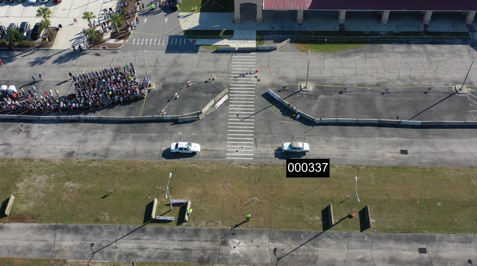
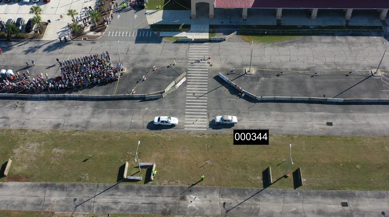
We'll load these two frames into an image editor and zoom in.
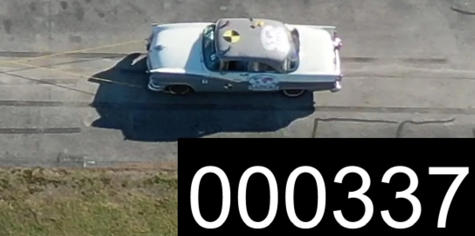
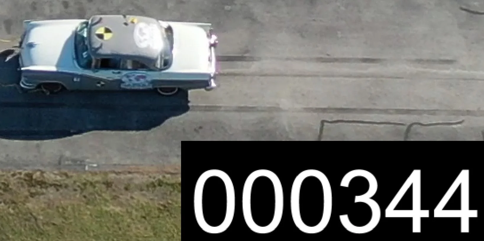
Both vehicles are pulled straight ahead into impact, so the displacement vector of the 1956 is roughly aligned with its own wheelbase. We’ll assume minimal lens distortion, and that the real-world displacement vector of the 1956 is parallel to the camera’s image plane. Then a single scale factor (r) tells us how many real-world distance units one pixel represents. We define r by:
r = WB / WBpx
with WB the known wheelbase in distance units and WBpx the same wheelbase measured in pixels. Any real-world displacement then follows from
D = r · dpx
where dpx is the displacement in pixels.
To find WBpx and dpx, load the two frames into any image editor that reports the cursor position in pixels. Read the (x, y) values of the front and rear wheel centers to get the wheelbase, and the (x, y) values of one identifiable point that moves between the frames, the front wheel center for instance, to get the displacement. The Pythagorean theorem gives each length.
We'll drop the frames straight into a new Virtual CRASH 6 project and use our own measuring tools within Virtual CRASH to get distances in pixel units.
Above, the two frames are placed in the VC6 project with pixel length and pixel width both set to 1 ft, so each pixel carries a physical scale of 1 ft by 1 ft. Any distance measured across the image plane with the 2D dimension line tool then reads directly in pixels: a result of 394 ft means 394 pixels. Both images sit at position-local (x, y) = (0, 0) so they lie exactly on top of one another.
Here we read WBpx = 394 pixels.
The wheelbase in physical units is 9.625 ft, so
r = 9.625 ft / 394 px = 0.02443 ft/px
Reducing the opacity of the second frame lets us see both positions at once and measure the front wheel displacement in pixels.
Here dpx = 443 pixels, since the image is scaled so one pixel reads as 1 ft. The real-world displacement is therefore
D = r · dpx = (9.625 ft / 394 px) × 443 px = 10.82 ft
This occurred over seven frame intervals between frame 337 and frame 344, so
dt = 7 frames / 29.97 fps = 0.234 s
giving
v = 10.82 ft / 0.234 s = 46.33 ft/s = 31.6 mph
This sits right at the known pre-impact speed of the 1956 (see below).
For views where the displacement you're tracking runs parallel to the camera’s image plane, and where lens distortion is negligible, this method can work well. Any image editor will do, or you can drop the frames into Virtual CRASH. You just need a way to measure distances in pixel units.
But what about a displacement with a component along the camera axis, a vehicle travelling toward or away from the camera? Then r is no longer constant. It varies with distance from the camera, and so changes as the object moves through the frame. That is where the more advanced methods come in. The mathematics is not sophisticated by reconstruction standards, it just requires some extra accounting for how r varies. You could do it in a spreadsheet. Read on below to learn about PLA.




Projected Length Analysis Speed Estimators
The Length Scale Tracking method tracks the image scale r explicitly as the object moves through the frame and uses it to correct the estimated displacement. It requires only that a feature of known length be visible in at least two frames, and it extends to a full frame by frame sequence without modification. Tracking the endpoints of that feature in every frame, a wheelbase for instance, rather than measuring it once, gives r wherever it is needed. That is what allows perspective change across the interval to be accounted for rather than assumed away.
The second solver takes a different route to the same answer. The cross ratio is a quantity formed from four points on a line that a perspective projection leaves unchanged. The rear and front wheel in the first frame, and the same two in the second, give exactly four such points. Two of the three spacings among them are already known, since the wheelbase appears twice, which leaves the displacement as the only unknown. Measuring the cross ratio in the image and setting it equal to its real-world value therefore yields one equation in one unknown, and the displacement follows directly.
The central assumption of both methods is that the object's real-world displacement is parallel to the known-length feature, since it is that parallelism that makes perspective foreshortening cancel between the two measurements. Note: the Video and Image Analysis tool makes no such assumption, since points of interest are tracked explicitly through 3D space.
Let's run the same case through the PLA estimator, available here (note if you have trouble logging on, try opening in your browser's incognito mode), to see how it compares to the method discussed above.
The setup starts as before. Drag and drop the video into the Virtual CRASH project, dropping it directly onto the x-y plane (rather than onto a camera background). Set the position to (0, 0) and both pixel length and pixel width to 1 ft, so one pixel measures 1 ft square.
With the time-min and time-max values set in the video’s “misc” menu, we're working on the same eight frames as before.
Next, go to tools > object tracking, and press the “manual track point” button.
We create two tracks. Track 1 follows the front wheel contact patch, Track 2 follows the rear wheel contact patch, both across the same three frames. When you finish the first track, right-click to begin the next. Right-click twice to leave point-adding mode, then close the speed graph that opens automatically since it’s irrelevant for this analysis.
Both tracks must sit on the same frames. The estimator pairs the two datasets by timestamp, so a frame present in one track and missing from the other is dropped without comment in our analyzer. The paired front and rear points give the apparent length of the fixed feature, the wheelbase here, as the distance between them on the image plane in pixels. Our analyzer reports how many rows matched, so check that figure against the number of frames you tracked.
If you need to correct a track, select the video, press [Shift+T] then [F3], choose a track from the list in the object tracking menu, and use the yellow control grips to adjust point position and timing.
Next, open the dynamics report. It lists the (time, x, y, z) values for every point we clicked. Track 1 holds the front axle points, Track 2 the rear axle points, sampled at the same frames.
First copy the Track 1 data from the dynamics report, open the PLA estimator (note if you have trouble logging on, try opening in your browser's incognito mode), press “Clear points” to remove the sample data, click into the “Front feature” box and paste with Ctrl+V.
Repeat this process for Track 2 in the Rear feature box. Enter the fixed length, the wheelbase in this case, and the pixel uncertainty, which is the range within which you could reasonably place the feature while tracking. Then press “Calculate speed”.
The result appears on the right. Using a constant speed model we get 31.41 ± 0.43 mph, against 31.6 mph from the “hand calculation” earlier and in close agreement with the known crash test speed.
In the results section, the “Distance estimator” dropdown switches between Length scale tracking and Cross ratio. The “Motion model” dropdown beside it gives you the choice to use a uniform acceleration fit for cases where the vehicle is speeding up or slowing down across the track points.
Manual point tracking requires at least three track points, but a two-point estimate is still available. Delete the second row from both the front and rear datasets, press “Calculate speed” again, and you reproduce the results from the manual calculation above.
Example | Object moving away from camera
The example loaded when you first open the PLA estimator (note if you have trouble logging on, try opening in your browser's incognito mode) gives an estimated pre-impact speed of about 43 mph against a known crash test speed of 42.2 mph for this WREX 2023 Crash Test 13 video.
Example | Object moving TOWARD camera
The example below comes from Crash Test 1 at the 2025 IPTM Symposium, a 60 mph test.
Example | Dash Cam
This example returns to WREX 2023 CT3, this time using the camera mounted on the 1956. The crosswalk stripes move toward the camera, and the camera's real-world displacement is aligned with the fourth stripe from the left. A two-point fit tracking the near and far ends of that 16 ft stripe yields a pre-impact speed estimate within 10% of the value shown on the video. For this workflow, choose features such as skip lines whose real-world axis aligns as closely as possible with the camera's direction of travel.
Example | dashcam in motion, object in motion
Continuing with the moving camera from WREX 2023 CT3, we can estimate the closing speed between the 1956 and the oncoming 2007 Ford Crown Victoria using a feature of known length on the 2007. The wheels are hard to make out here, so we use the distance from the frontmost corner of the driver side window to the rearmost corner, measured from our point cloud.
We'll use three track points just prior to impact. The white stripe analysis above gave the 1956 a pre-impact ground speed of 28.04 ± 1.98 mph, and tracking the 2007 gives a closing speed of 62.18 ± 4.08 mph. The difference is the ground speed of the 2007 (the two estimates are separate features, separate frames and separate reference lengths, so we treat estimates as independent and combine in quadrature, sqrt(4.08² + 1.98²) = 4.54): 34.14 ± 4.54 mph.
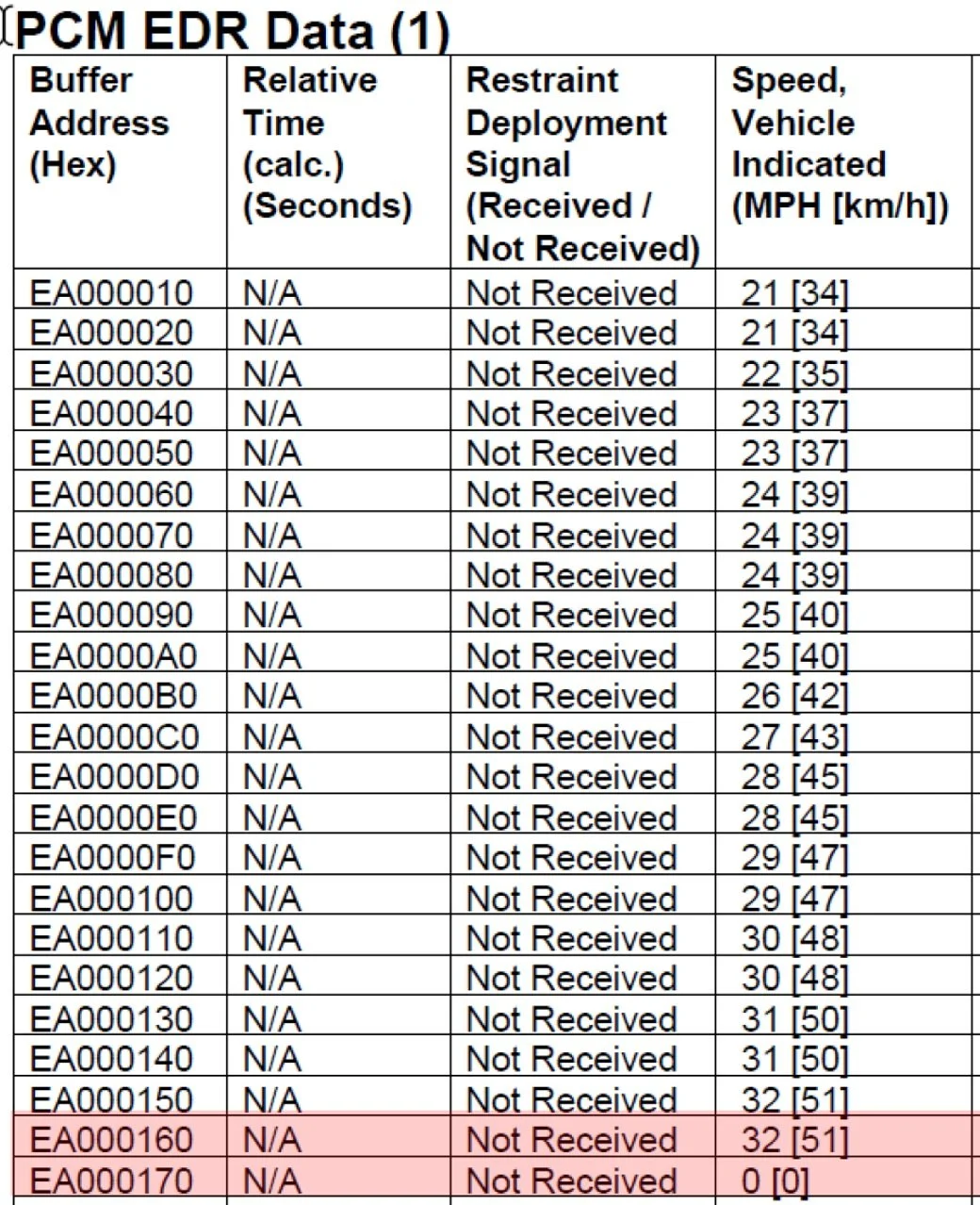
The 2007's EDR report gives a pre-impact speed of 32 mph, inside the uncertainty range from our PLA-based analysis.
Where EDR data existed for the oncoming vehicle and it was visible on camera, but no ground stripes were available, the same subtraction runs the other way. Closing speed minus the EDR speed gives an implied ground speed for the 1956 of 30.18 ± 4.13 mph, which agrees with the 28.04 ± 1.98 mph.
Example | Motorcycle T-bone crash Caught on Camera
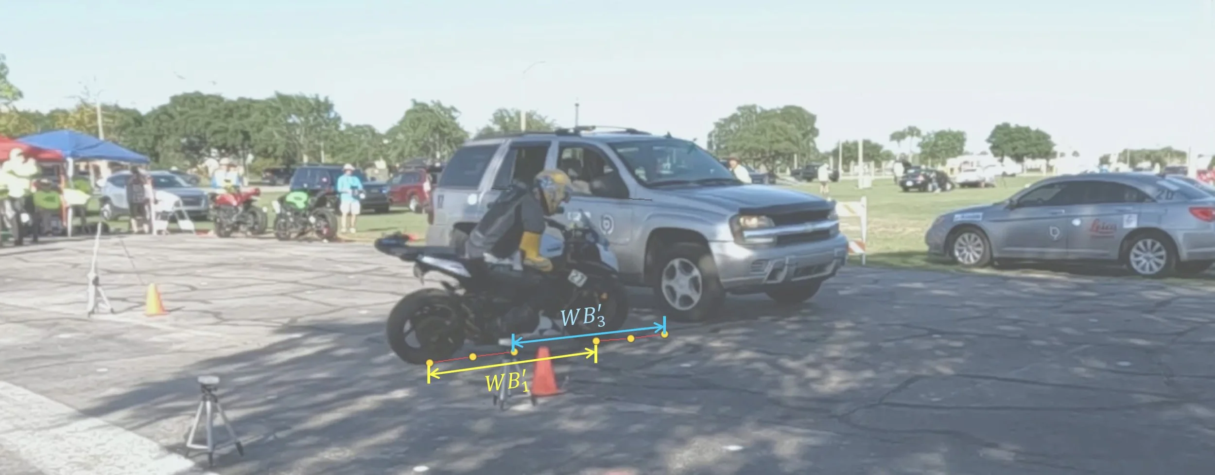
In this example, from WREX 2023 CT23, a 2013 Kawasaki Ninja 1000 struck the side of a 2006 Chevrolet TrailBlazer.
Using the corners of the passenger side windows as our fixed length, we obtain a pre-impact speed estimate for the TrailBlazer of 15.36 ± 1.35 mph, against a VBOX reported value of about 14.1 mph.
Tracking the same frames using the motorcycle's wheelbase gives a PLA pre-impact speed of 37.55 ± 0.90 mph, against VBOX data showing about 36 mph just before impact.
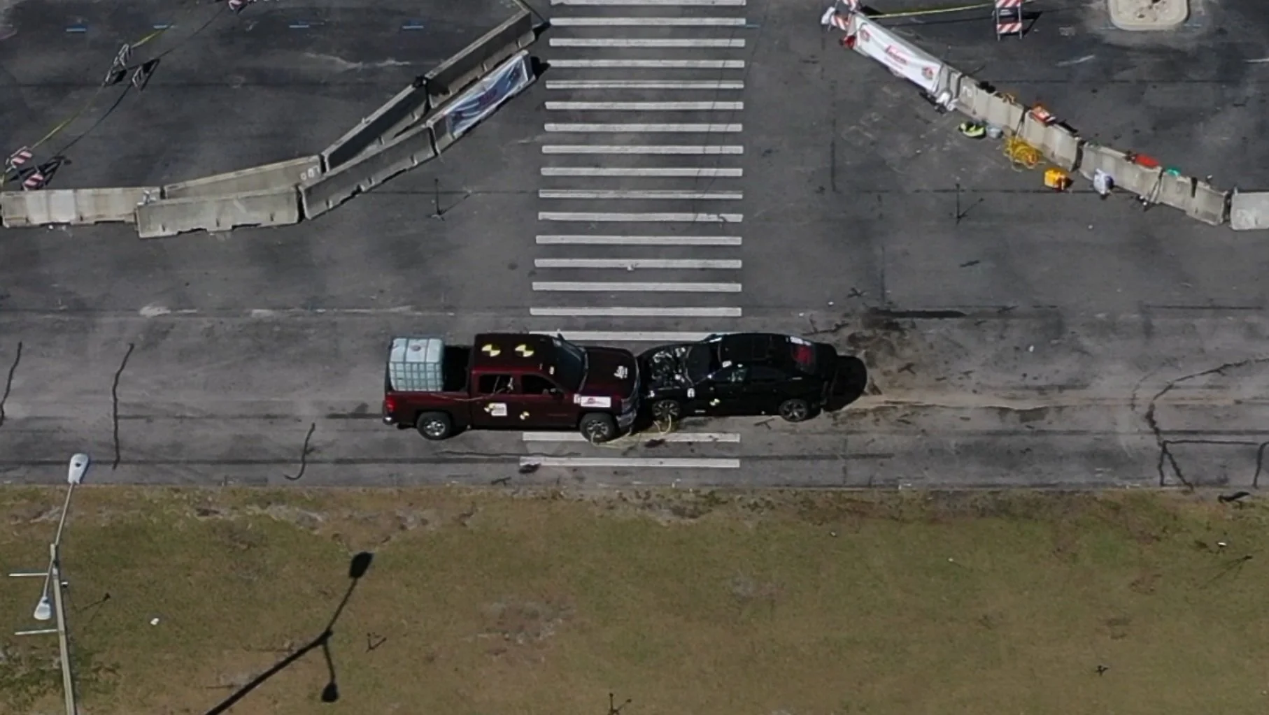
Example | Head-on collision
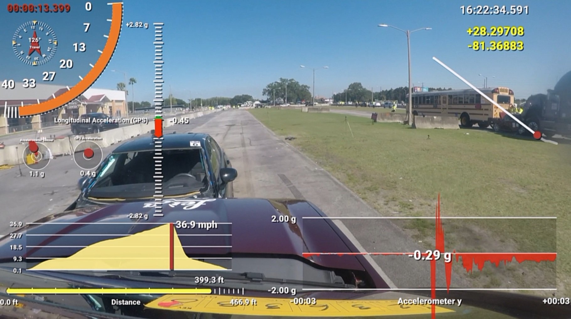
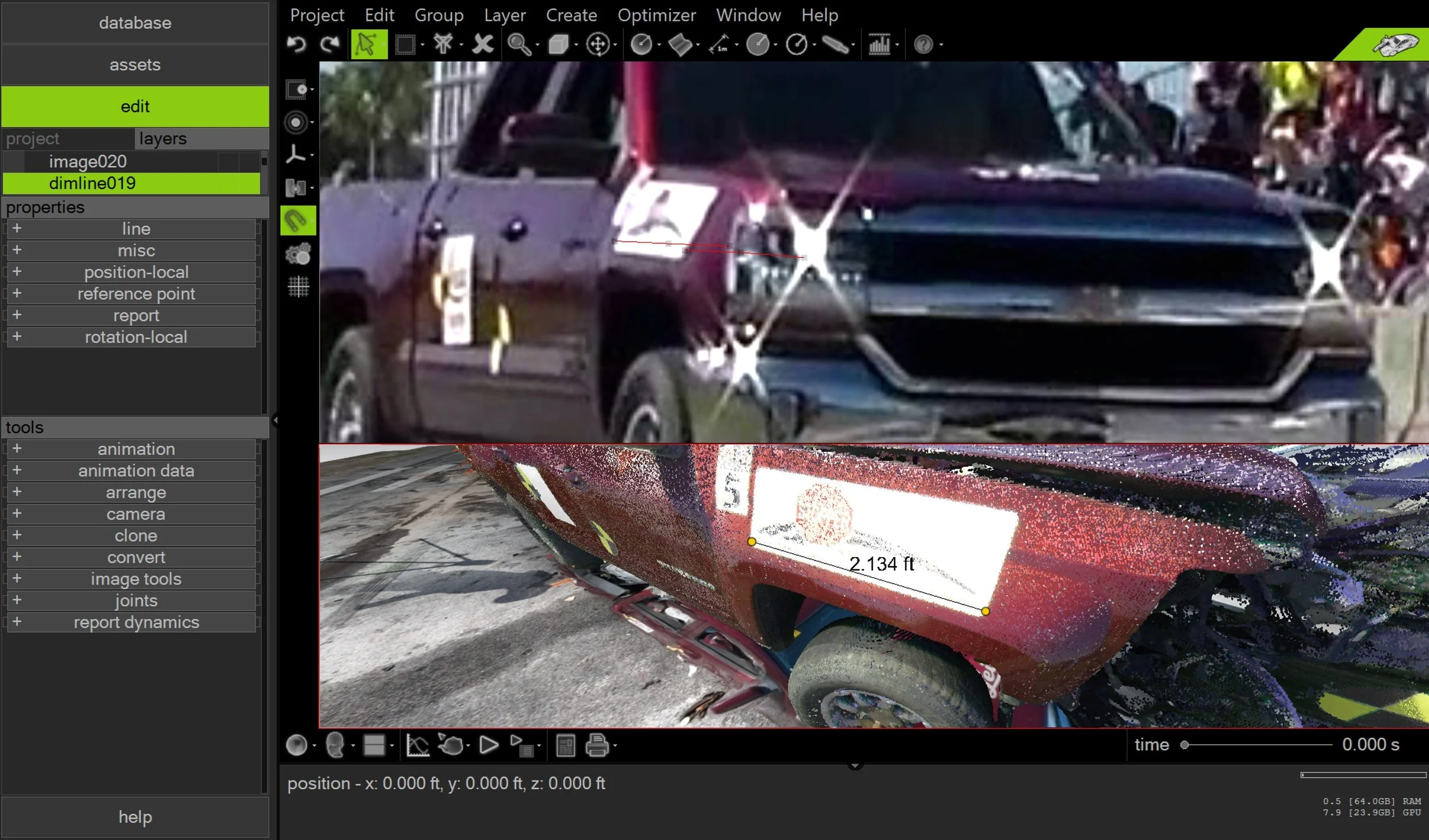
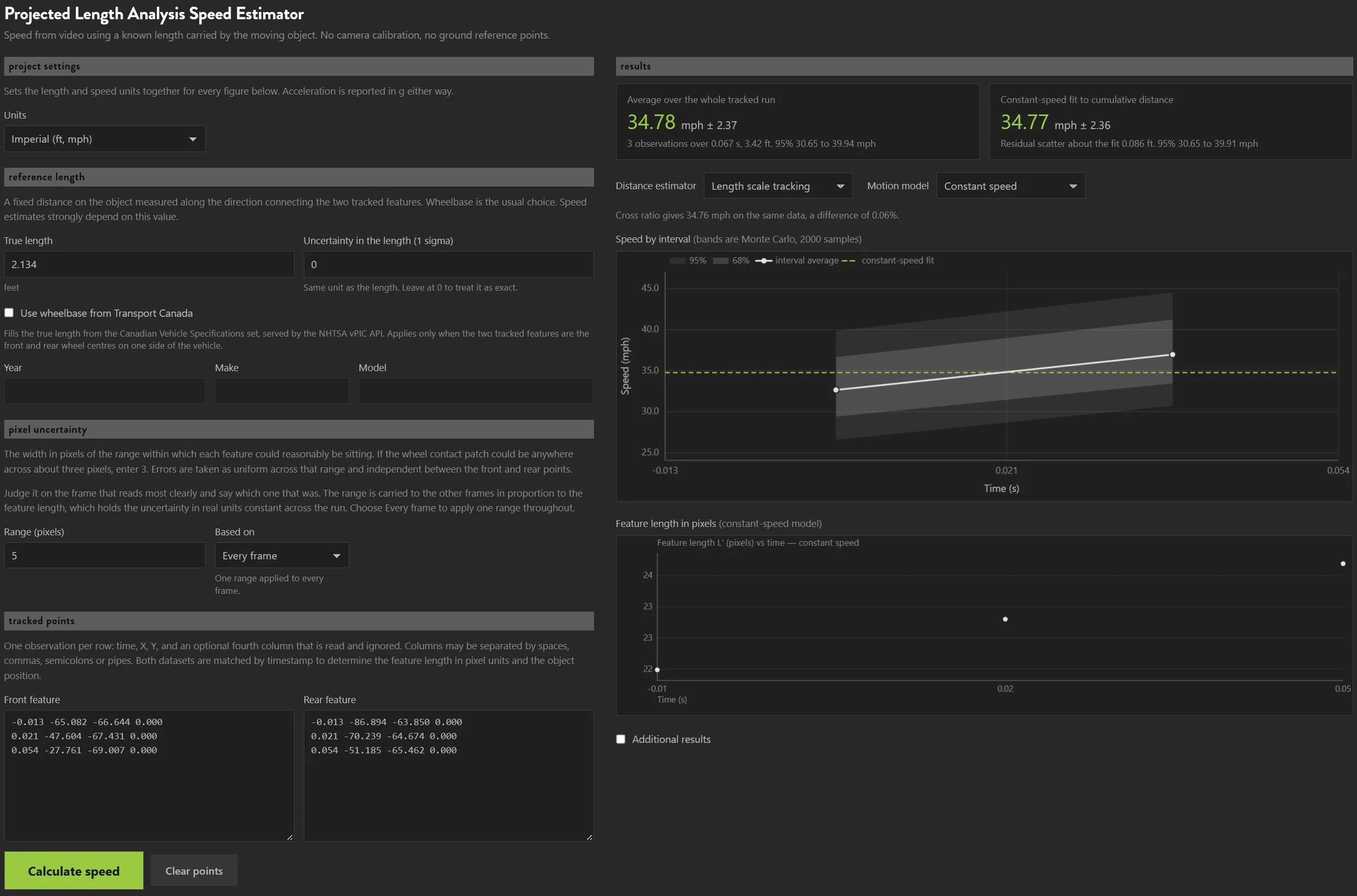
In this example, we use a decal mounted on the front passenger side, approximately aligned with the longitudinal axis of the subject 2017 Chevrolet Silverado. The final three frames prior to impact were used, so the decal was tracked over a very short time interval. The decal length was measured directly from the vehicle scan. The PLA-based speed estimate of 34.78 mph ± 2.37 mph is consistent with the VBOX reported speed of 36.9 mph (see video).
Example | Video of a Video
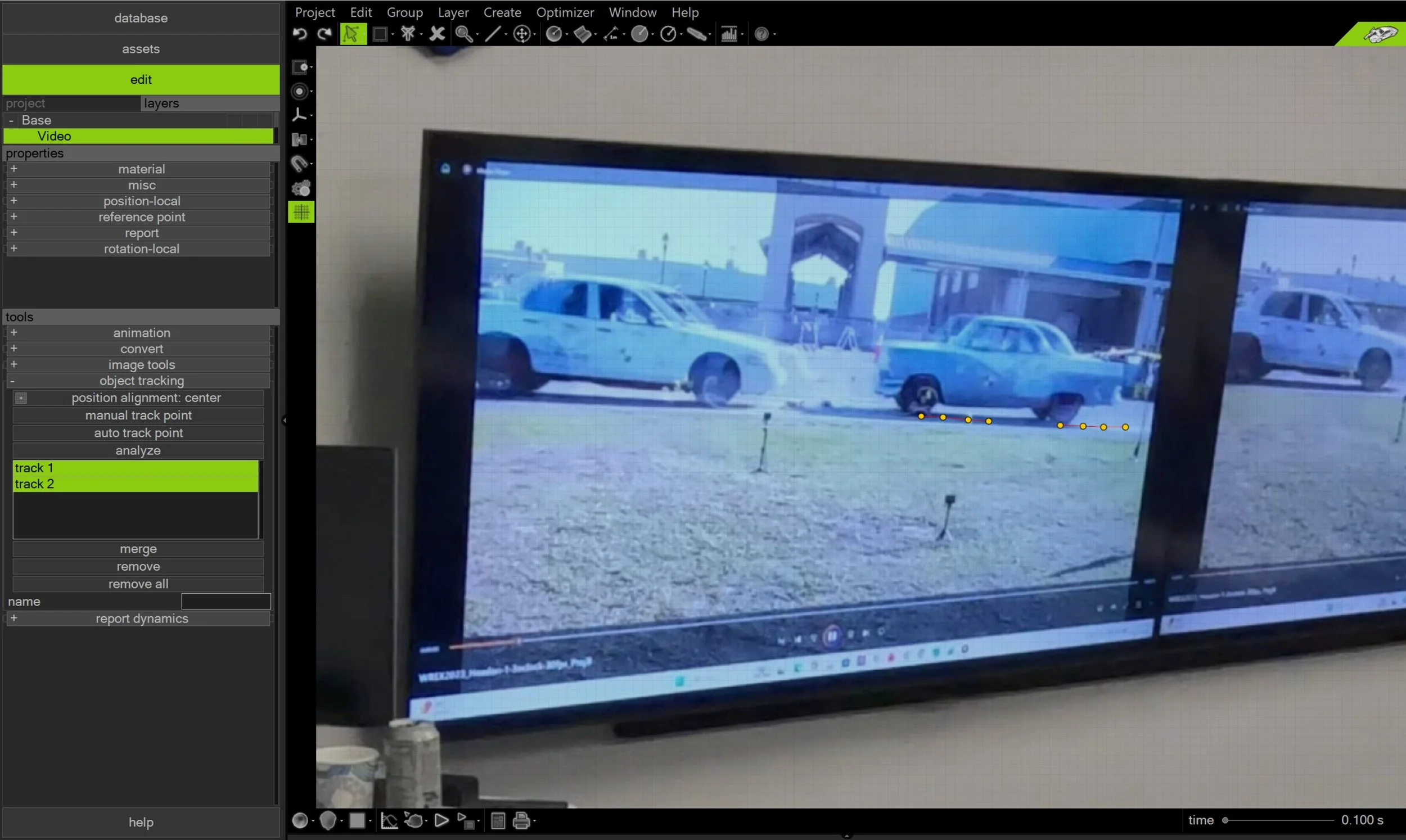
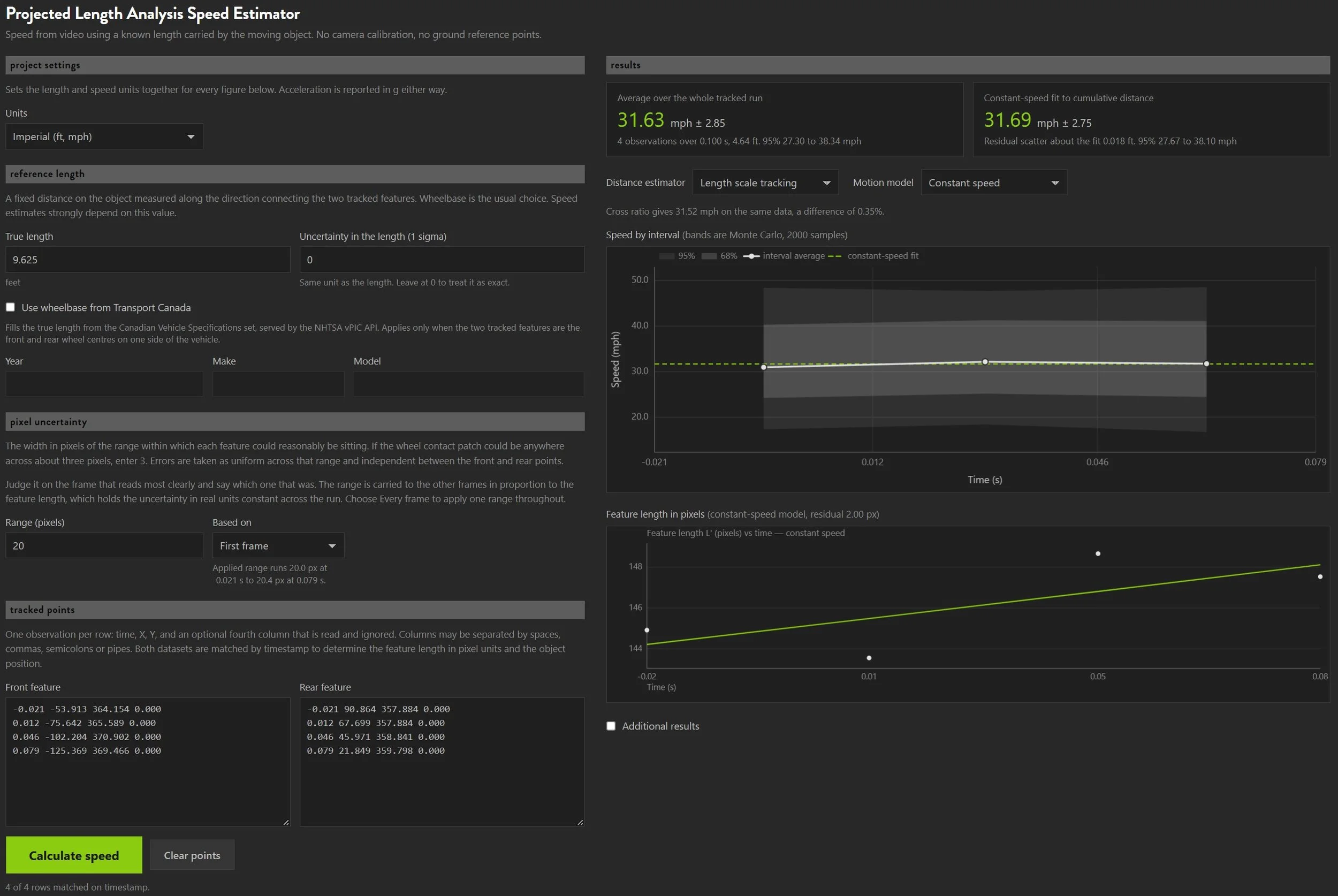
In the example below, a 29.97 fps video of WREX 2023 Crash Test 3 was played in Windows Media Player on a television during a private Virtual CRASH training class. A stationary camera recording at the same frame rate was used to capture the television screen. That camera recording of the screen, not the original test video, was imported into Virtual CRASH for point tracking. A pre-impact speed of 31.63 mph ± 2.85 mph was obtained for the 1956 Ford Victoria, against a VBOX reported speed of 31.6 mph.
Example | Walking / Running speed analysis
This example uses a simulated fast walker with a known gait. Track 1 follows the toe of the trailing foot across three frames, and Track 2 follows the heel of the leading foot across the same frames. The known heel-to-toe distance at full stride served as the fixed length. The resulting walking speed estimate came within 5% of the simulated value.
Cameras in Motion | Non-stationary Cameras
A handheld camera pans, shakes, and zooms, so a vehicle's apparent movement on screen mixes its own motion with the camera's. Reference point tracking corrects this using fixed ground features such as pavement marks or sign bases. Because these points don't move, any shift they show comes from the camera. Tracking at least four of them in the same frames as the vehicle lets our estimator measure and remove that camera motion. Front and rear points on the vehicle, whose separation is known, provide the scale in each frame.
Footage that is a phone recording of a video playing on a screen adds a second camera, and each one can be stationary or moving:
Both stationary: The ground points stay fixed, and no correction is needed.
Original camera moving, re-recording steady: The ground points capture the original camera's motion.
Original camera steady, re-recording handheld: The ground points capture the phone's motion relative to the screen, including any angle to the screen.
Both moving: The ground points capture the combined motion of both.
In every case the correction is the same. Both layers of camera motion move the whole image together, so the ground points record their combined effect, and our estimator removes it in a single step. The analyst doesn't need to know which camera moved or by how much, only that enough ground features are visible in the original footage.
Below we review two common situations: handheld footage of the event, and a handheld recording of handheld footage.
Example | Handheld Camera
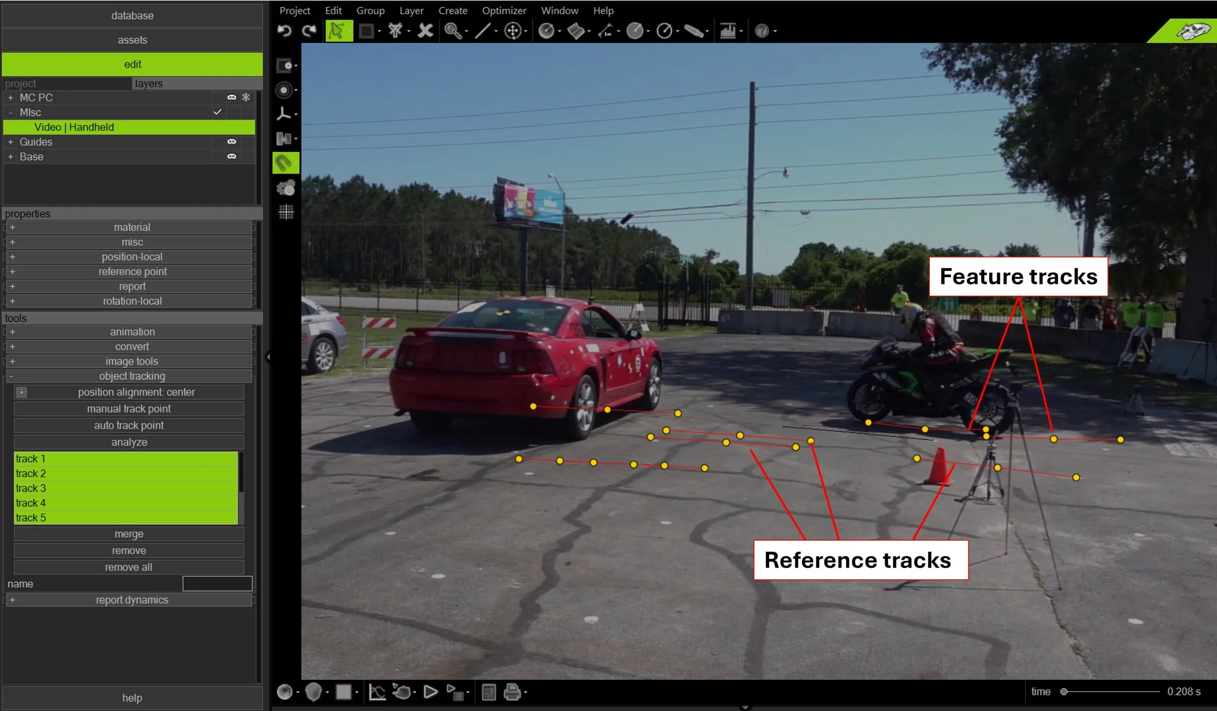
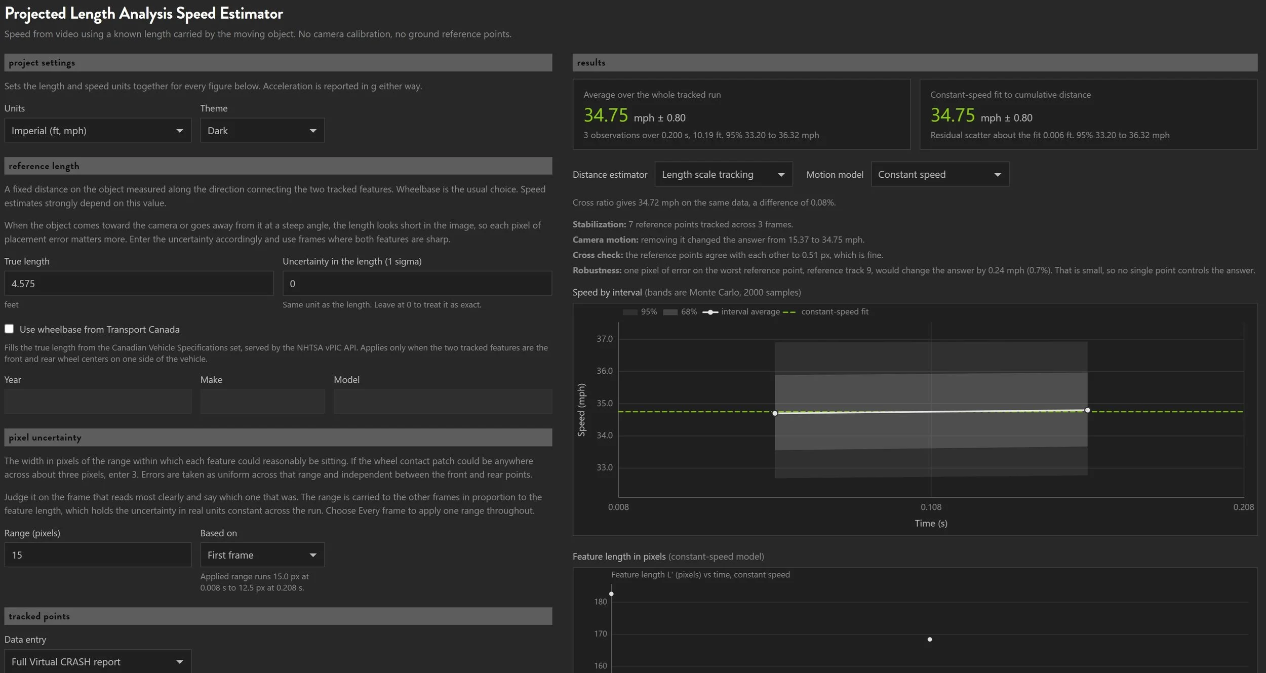
In this example, from WREX 2023 CT19, a 2014 Kawasaki Ninja ZX-6R motorcycle struck the side of a 2003 Ford Mustang at a measured speed of 34 to 35 mph. Using the motorcycle's wheelbase and 7 ground reference points, the PLA speed estimate is 34.75 ± 0.80 mph.
Example | Handheld Camera Records Video from Another Handheld Camera
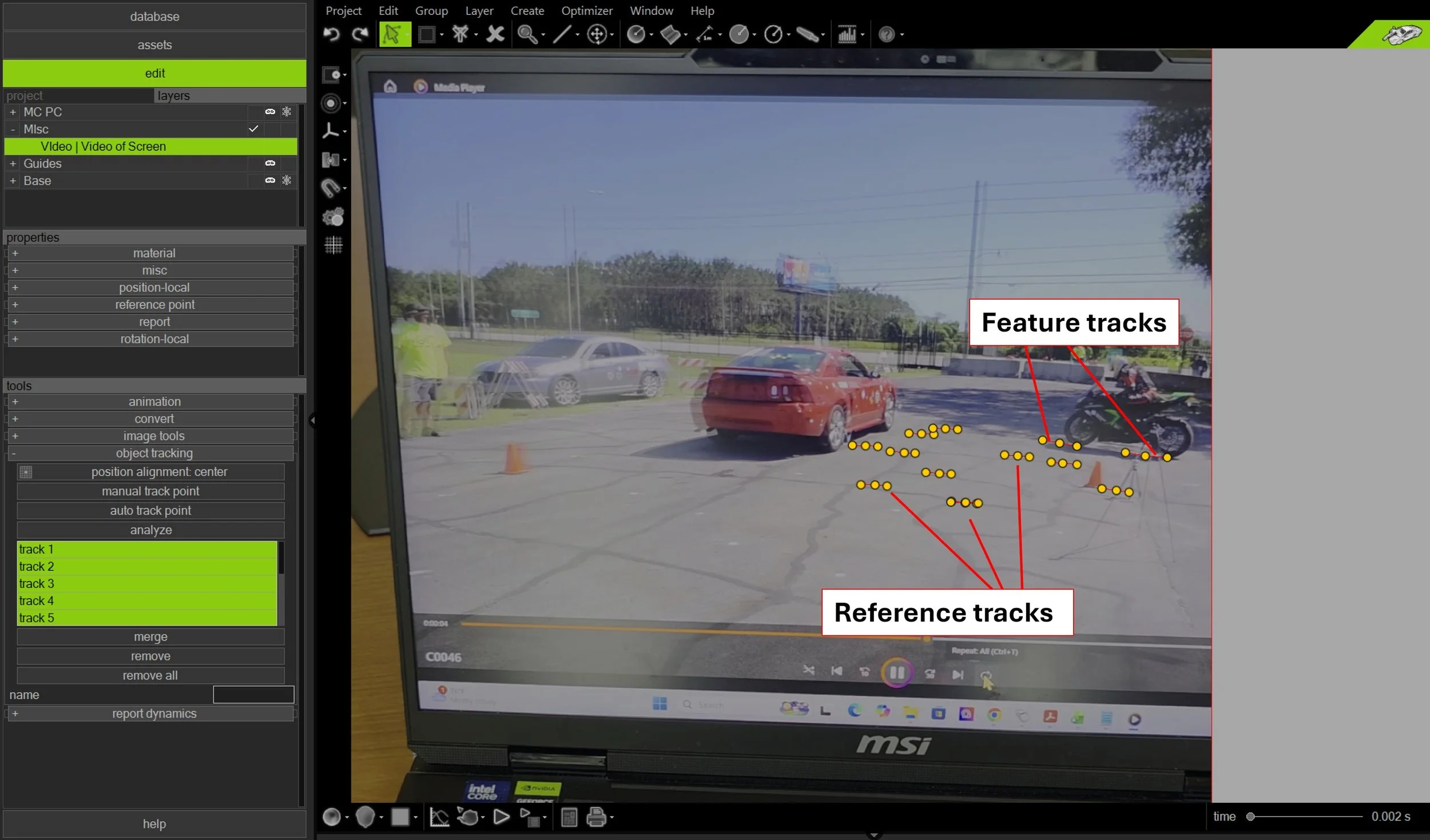
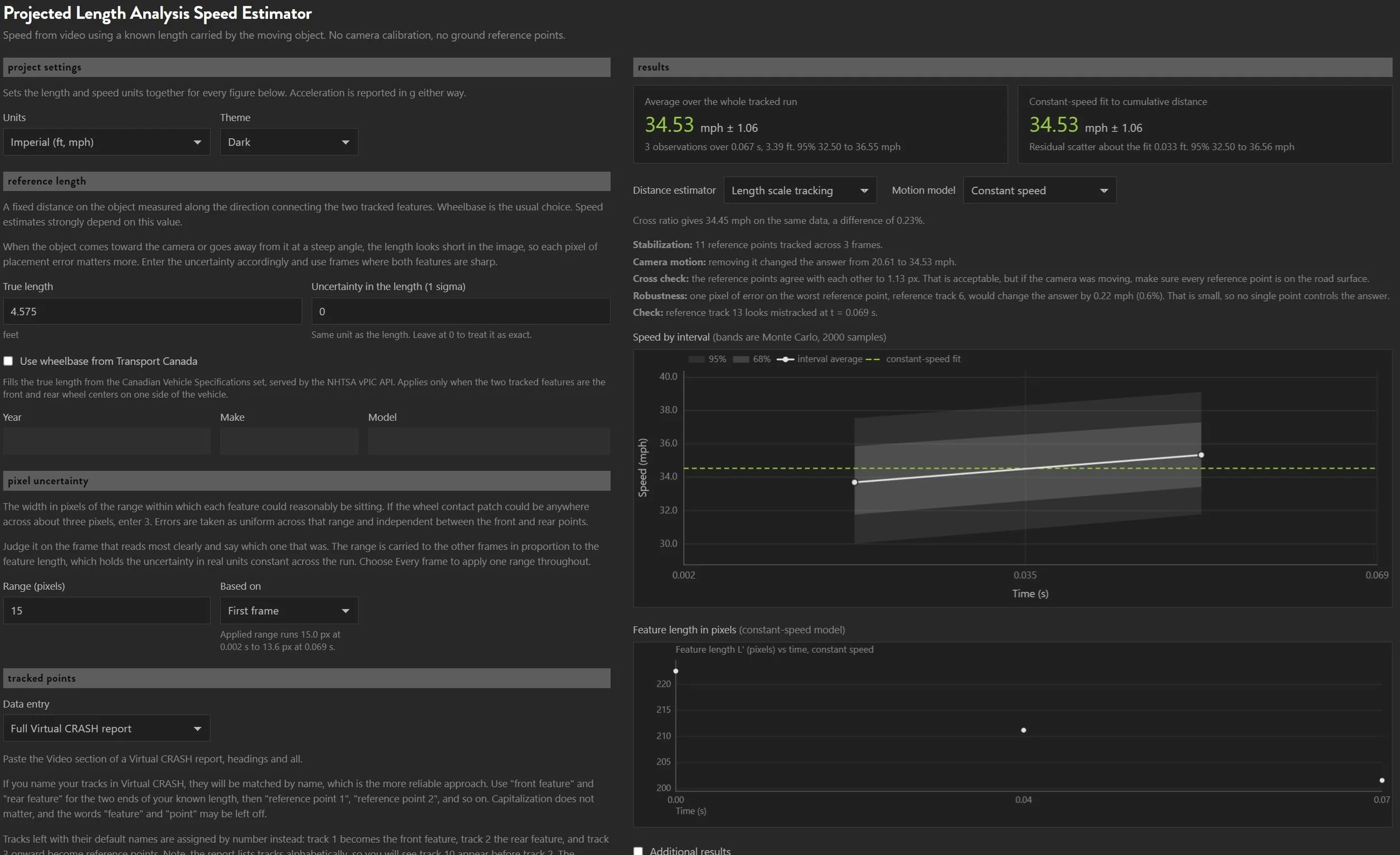
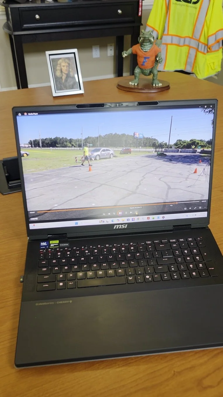
In this example, again from WREX 2023 CT19, a 2014 Kawasaki Ninja ZX-6R motorcycle struck the side of a 2003 Ford Mustang at a measured speed of 34 to 35 mph. This time, the points were selected in a phone recording of the original video playing on a laptop monitor. Using the motorcycle's wheelbase and 11 ground reference points, the PLA speed estimate is 34.53 ± 1.06 mph.
Example | Vehicle-Mounted Camera in Motion
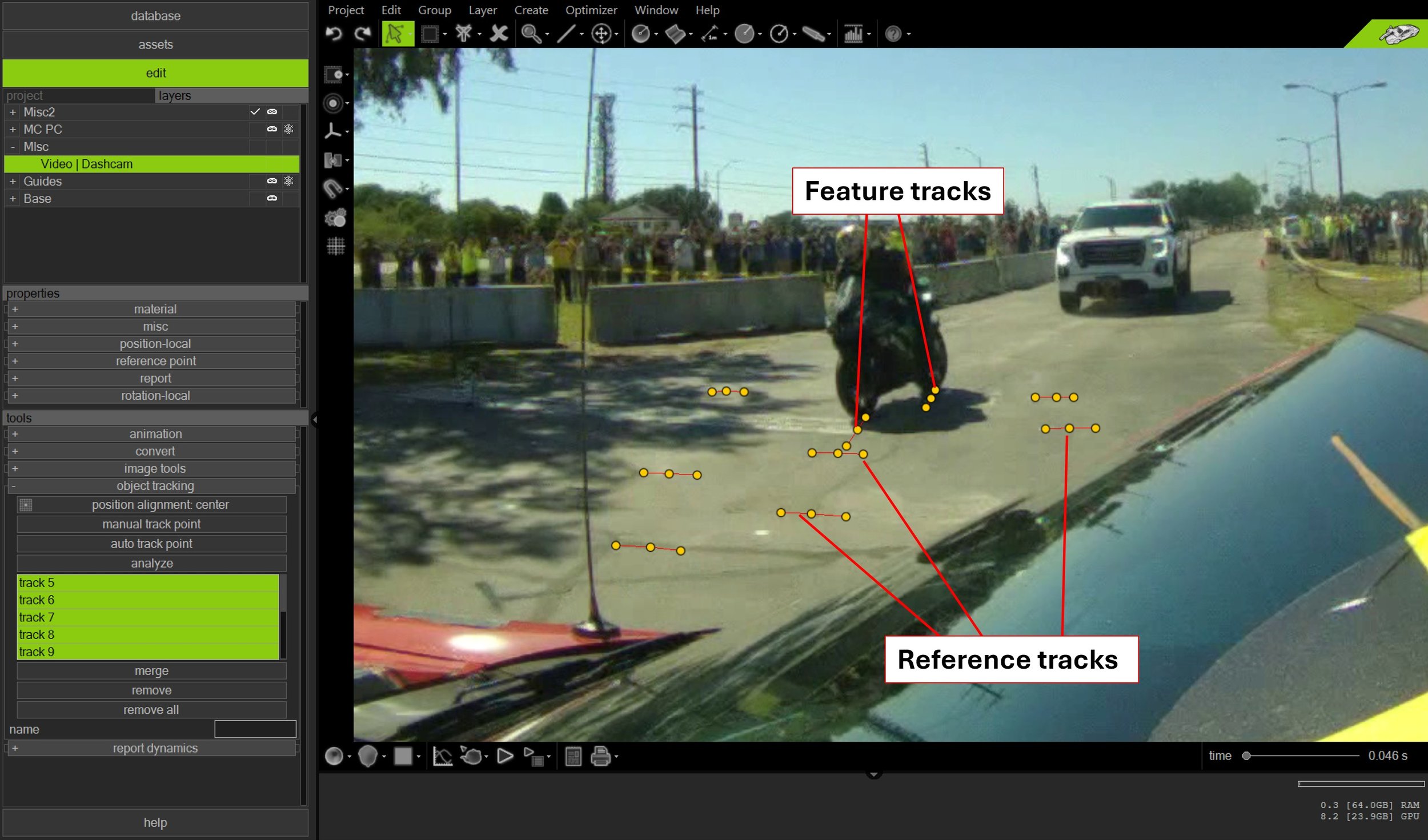
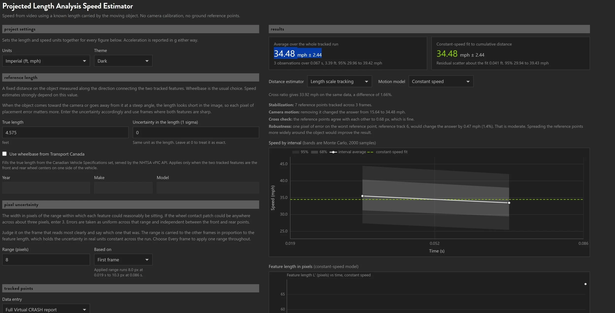
In this example, also from WREX 2023 CT19, a 2014 Kawasaki Ninja ZX-6R motorcycle struck the side of a 2003 Ford Mustang at a measured speed of 34 to 35 mph. This time, the points were selected in video from a camera mounted on the Mustang, facing the motorcycle as it approached. Using the motorcycle's wheelbase and 7 ground reference points, the PLA speed estimate is 34.48 ± 2.44 mph. Note that in this example the reference point tracks run nearly transverse to the motorcycle's pre-impact trajectory.
References
[1] Cross-ratio solver after Y. Choi, J. Park, Y. Yun, W.-J. Jeon and S.-H. Kong, "Cross-ratio and vehicle dynamics-based speed estimation for traffic accident analysis," Forensic Science International 378 (2026) 112675. doi:10.1016/j.forsciint.2025.112675