

Blog | All About Reference Points
Updated: 4/27/2021
The Summer 2019 Software Update included a much-anticipated feature which makes it easier for Virtual CRASH 4 users to position images, point arrays, and point clouds with respect to a global coordinate system. Prior to this update, users had to follow a more complex multi-step process to position data within a global coordinate system.
The way the new positioning feature works is by using a new “reference point” attribute. Below we explain this new attribute using scene data from Crash Test #1 of the 2019 IPTM Symposium on Traffic Safety.
Images
To create this orthomosaic image, a DJI Mavic 2 Pro was flown over the scene to collect a series of images. The images were then processed by Pix4D to generate the orthomosaic and point cloud. Here we set the image’s position-local value to (0,0) which places it at (0,0) in the Virtual CRASH frame coordinate system. Below we placed a red circle at (0,0) to highlight the origin.
Here we see the tfw file from Pix4D.
The TFW file can be used to both scale and position the orthomosaic in global space. This can be done automatically by using the “load TFW file” option. Remember, you can always start your project by simply importing the TFW file first and use the Smart Alignment Tool to load and align your image with point cloud and total station/RTK data. In our example here, we’ve started by first importing the image, then we use the TFW file reader.
Now that we’ve loaded our TFW file, we see our image’s scale has been adjusted such that the physical pixel size matches what’s indicated in the TFW file. The upper left pixel position of the image has been placed at (0,0) in the Virtual CRASH frame.
To further explore this, let’s change location to (50,50) and reference point to (20,60). Here we see the image is now shifted and the upper left pixel center is no longer at (0,0) in the VC frame. Note the x’ and y’ axes are rotated 180 degrees with respect to the Virtual CRASH frame x and y axes. This is simply for convenience to keep the x and y value magnitudes and signs exactly equal for location and reference point when the TFW file is loaded.
Aligning Multiple Image Tiles | Preferred method as of 2019 Winter Software Update B
As of the 2019 Winter Software Update B, you can now import and automatically align image tiles in VC4. This is described below. Learn more about update >
As of the 2019 Winter Software Update B, you can specify a file folder of image tiles and corresponding .tfw files, and Virtual CRASH will automatically import, scale, and place the individual image tiles in your scene. This allows you maximize system resources where it is needed the most, and produce even more amazing visuals for your case.
(1) Start by placing the large orthomosaic with corresponding point cloud and point array file into same file folder. Make sure these assets have the same file name (they will all have different file extensions of course). In this folder, also include all image tiles and corresponding tfw files. Each tile should have the same file name as corresponding tfw file.
(2) Next, go to Project > Import. Simultaneously select all tfw files in your project folder that contains the orthomosaic and all image tiles. Left-click on “Open”.
(3) Now, you’ll see the Smart Alignment Tool import dialogue box. Set the units and other settings for the various assets you would like to load. Finally, set the image quality you would like to be applied to all images that will be imported. This quality setting will allow you to maximize your system’s resources versus the image quality necessary to generate the best looking visuals.
(4) You’ll then see all assets loaded and automatically aligned. The separate image tiles and orthomosaic will be grouped together. All images have a new parameter “texture quality” which can be set to any value between 1 to 100%. The higher the value, the better the image quality, but the more system memory that is required to use the image. You can modify the texture quality for all images at once, or one image at a time. When modifying the image quality, the best practice is to type in the numerical value into the image quality input field rather than using the slider.
The major advantage of this feature is that you can now fine-tune where you want to keep the highest image quality. For top-down overviews, lower image quality is typically acceptable since the ability to resolve fine details is diminished as the camera is placed further above the road surface. For driver’s perspective visuals, you’ll typically want to use higher quality images for the road surface near the camera. The trade-off between image quality versus system resources is now easily controlled.
Aligning Multiple Image Tiles | Legacy Method
Using the reference point attribute, multiple image tiles can be aligned (see blog post on exporting multiple image tiles from Pix4D). This process is shown in the video below.
Note, in the first example shown in the video, the reference point (x,y) values for all image tiles were set equal to the (x,y) value of the upper left pixel specified in the TFW file for the first tile. This positions the first tile in the scene such that its upper left corner pixel sits at (0,0) in the Virtual CRASH frame. All of the other tiles will be properly positioned around this first tile.

LOOKING FOR A NEW WORKSTATION, LAPTOP, OR DRONE?
See our Recommended Hardware page >
Notice the reference point x and y values have been changed as well as the “location” x and y values. The “location” attribute defines the position of the absolute (physical) global frame’s origin within the Virtual CRASH frame. The reference point x and y values then define the position of the image’s upper left pixel’s center with respect to this absolute frame origin. Notice both the location and reference point x and y values are equal to the values from the TFW file. This guarantees that the upper left pixel center comes in at (0,0) in the Virtual CRASH frame.
Below we see the true absolute (physical) location of the image tiles (not shown to scale), with the corresponding positions in the Virtual CRASH frame.
Since all of the reference point (x,y) values are the same, the position of each image tile with respect to the location (x,y) position is identical for all tiles. This means the images maintain their proper alignment relative to one another. You are free to set the reference point (x,y) values to any arbitrary value. As long as the values are the same for all image tiles, they will maintain proper relative alignment.
In the second example shown in the video, the image tiles were aligned with respect to the placement of the single large orthomosaic image. In this case we input the large orthomosaic image’s (x,y) position for the upper left pixel given by it’s TFW file as the reference point (x,y) values for all image tiles.
Point Cloud Imported without Point Array
Point cloud objects also have an adjustable reference point attribute. The “location” attribute for point clouds does not need to be set as it does for images since the point cloud data already has positioning data given by the coordinates themselves. The location position is set as the (x,y) position of point #1 in the point cloud dataset. The z position is set by the z value of the lowest point in the point cloud. This ensures that the lowest point sits on the x-y plane rather than below when the point cloud is imported into the scene. When the “load TFW file” option is used, the reference point (x,y) values are set to the same value as used for the upper left pixel position from the TFW file. This ensures that both the point cloud and the orthomosaic are shifted by the exact same displacement vector with respect to their absolute global space position, and thus are properly aligned.
Point Array Imported Without Point Cloud or With Point Cloud Using Smart Alignment Tool
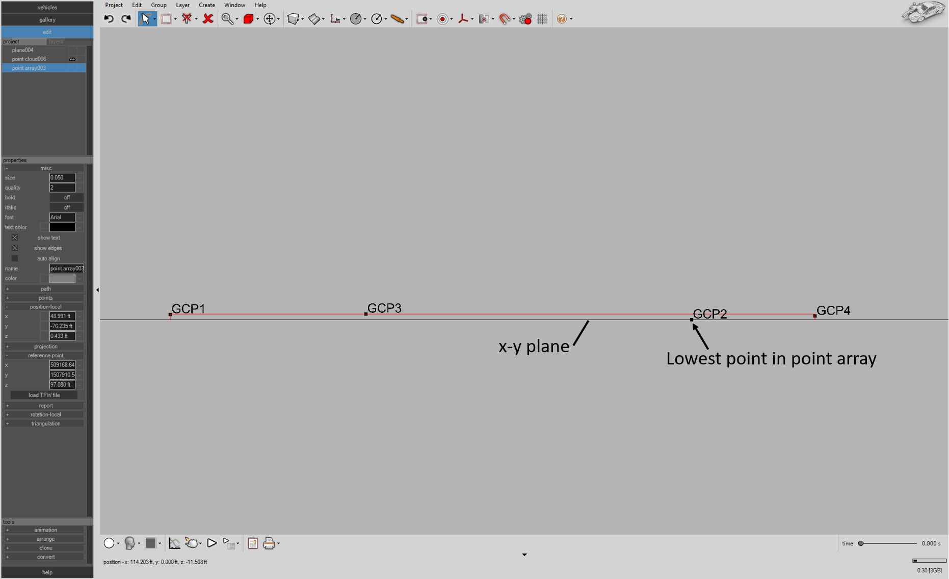
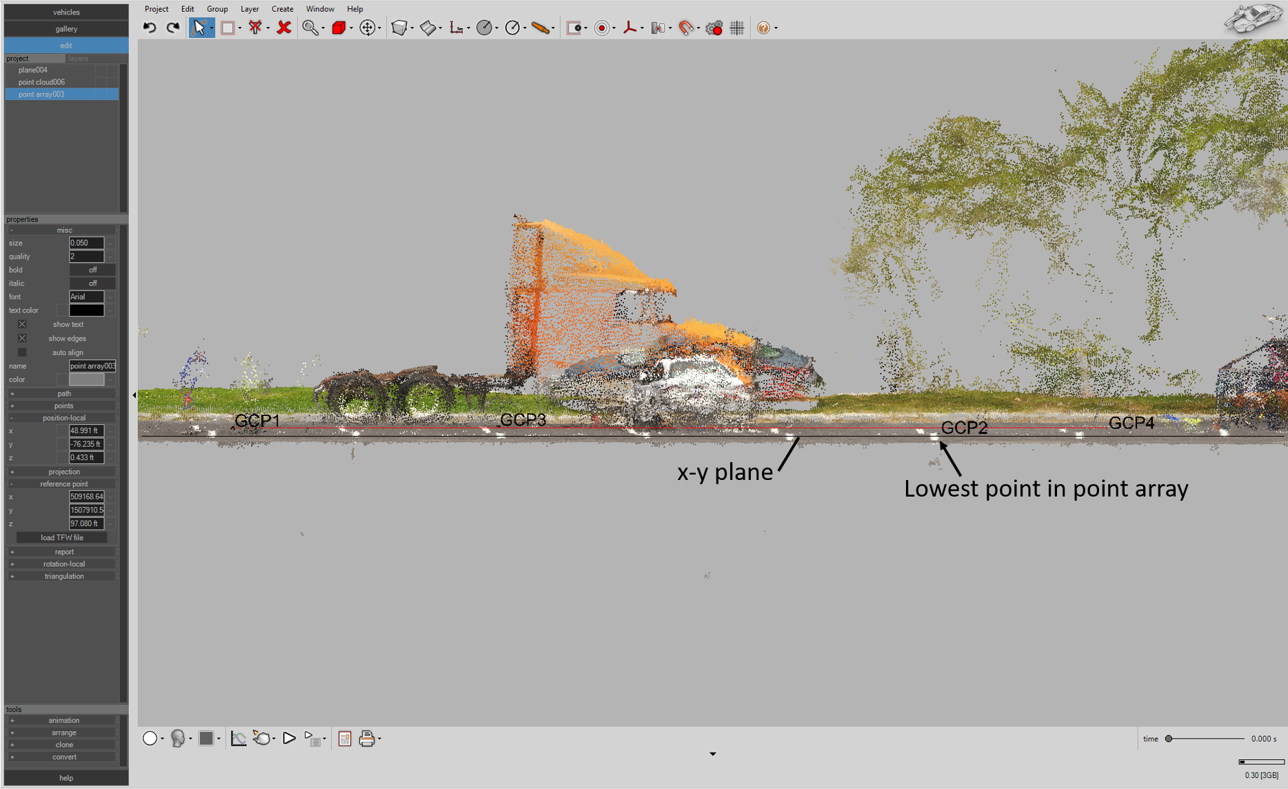
If a point array is imported into Virtual CRASH using a TFW file, the reference point (x,y) values are set to the position of the upper left pixel defined in the TFW file. The z reference point value of the point array is set to the lowest z value in the point array. This ensures the lowest point in the point array sits on the x-y plane.
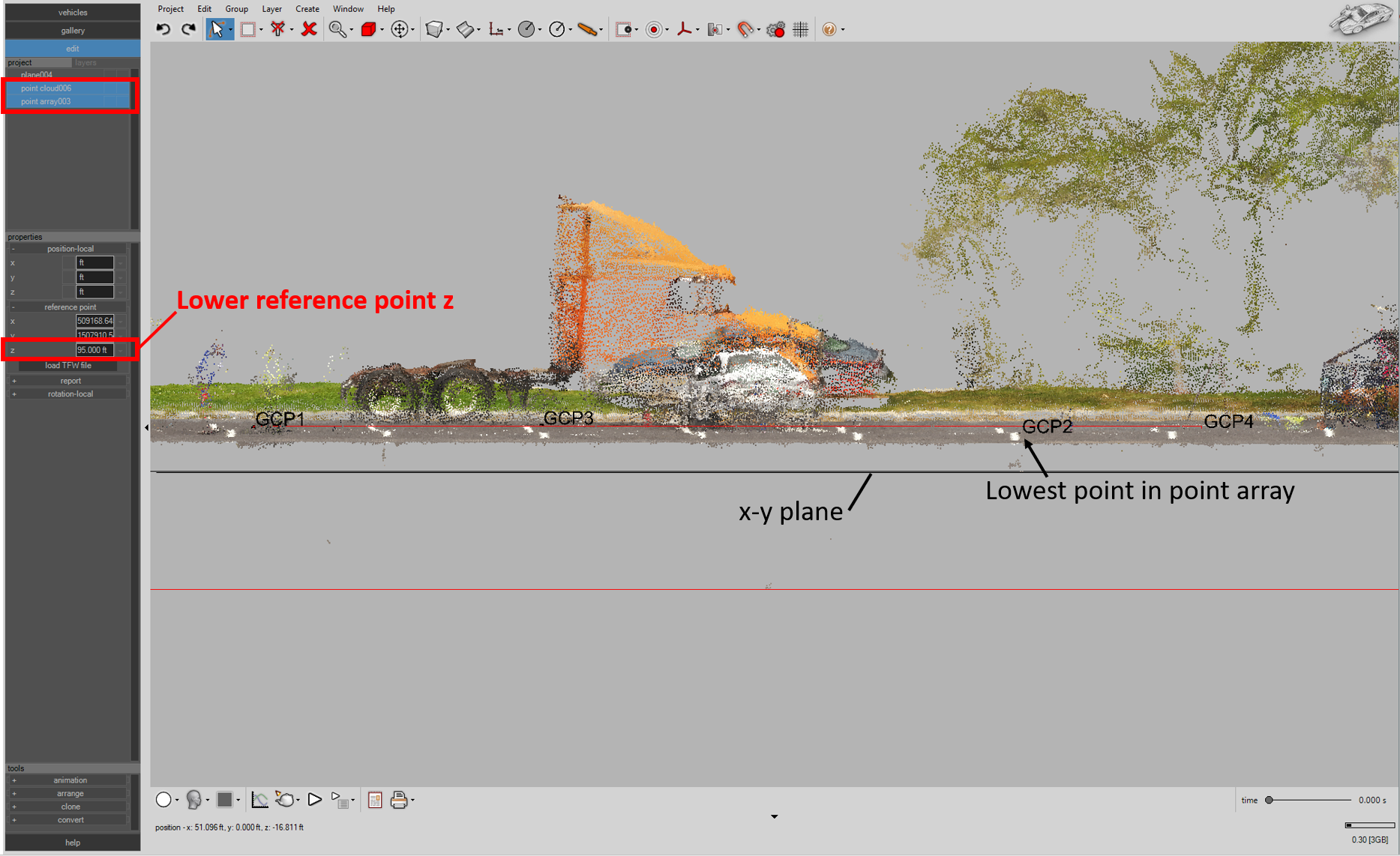
If both a point cloud and point array are imported at the same time with the Smart Alignment Tool, Virtual CRASH will set the point cloud and point array reference point values to the (x,y) value of the upper left pixel defined in the TFW file. Prior to the Summer 2019 Software Update, the z reference point value of both the point array and point cloud was set to the lowest z value in the point array. This means the point array was imported such that the lowest point sat on the x-y plane, with the point cloud positioned properly in z with respect to the point array. The potentially resulted in point cloud points sitting beneath the x-y plane. If this occurs, simply adjust the reference point z position for the point cloud and point array to a value (the same value) that brings all point cloud points above the x-y plane. This is illustrated below. As of the Summer 2019 Software Update, once the point cloud is fully loaded into your environment, its z-position will be set such that the lowest point in the point cloud will sit on the x-y plane (z=0). The z-position of the point array will then be automatically adjusted such that it’s automatically aligned with respect to the point cloud.
Placing objects at their absolute global position
If you want to place your orthomosaic, point cloud, or point array at its absolute global position in Virtual CRASH, simply set the reference point x,y, and z values to (0,0,0).