

Chapter 2 | Interface Basics and Mouse Cursor Controls

Introduction
This chapter provides a basic overview of the Virtual CRASH 6 workspace. More detailed information, including specific workflows and features, will be covered in the subsequent chapters.
Overview
The Virtual CRASH 6 workspace is divided into several major sections, as shown below. The Menu Bar, in dark blue, includes many commands that can also be accessed using the icons in the Upper Toolbar (green area) and the Side Toolbar (purple area). In the Menu Bar, you'll find standard file functions like "open" and "save," as well as geometric primitive shape functions such as "draw sphere" and "draw box."
In the Side Toolbar, features like the snaps toggle and control (magnet icon), the gridlines toggle (grid icon), and the motion control toggle (gears icon) are available. The Lower Toolbar, in light blue, offers controls like the interactive display mode (sphere icon), camera perspective (head icon), and motion playback control (play button icon). The time-slider and time input field are situated in the Time Controller area, indicated in yellow.
Memory resource monitors
The Memory Resource Monitor, outlined in black, allows you to monitor your system memory (RAM) and graphics card memory (GPU). As you build your projects, it's important to keep a close eye on these monitors to ensure you do not exceed the maximum available memory, which could lead to file corruption and other unwanted effects. The monitors will start blinking as you approach the upper limits. Remember, because Virtual CRASH 6 uses real-time rendering, productions can be very GPU intensive.
Left-Side Control Panel
The left-side control panel has three major parts. Left-clicking on “assets” (in red below) will take you to the vehicle and object assets browser. New vehicles can be placed in the scene by using the assets browser. This process is described in detail in the Prelude. By left-clicking on “help” (in yellow below), the Virtual Tutor menu will open. Double-left-click on any of the lessons to see how the various features work. See the Prelude for more detail on how to play a Virtual Tutor lesson. Left-clicking the “edit” button (black outline below), will return you to the home screen (default view) of Virtual CRASH 6.
Edit menu
When you left-click “edit” in the left-side control panel, you will be taken to the home screen or primary view mode for your project. This gives you access to the project menu, the properties menu, and the tools menu. In the project menu, you can select any object that has been placed into the project and modify its properties in the properties menu, so long as it is not frozen or hidden (discussed below). The options displayed in the properties menu will depend on what type of object is actively selected (indicated by its name being highlighted in the project menu or layer view and by a visible bounding box appearing around it in the workspace). If no object is selected, the options displayed within the properties menu will be related to the project itself. Additional options are available in the tools menu. For example, you can create videos of your animated motion by left-clicking the “animation” button to reveal its submenu and choosing the appropriate options (creating videos is described in the chapters below).
In order to see all items in the project menu, it may be necessary to move the properties menu down in the left-side control panel. Similarly, you may need to move the tools menu down in order to see all options in the properties menu or move the tools menu up to see the various tools menu options. To move a menu, simply left-click on the menu heading bar and hold, then drag your mouse up or down.
In cases where the menu contains more objects than can be displayed simultaneously in the left-side control panel, simply hover your cursor within the menu and use your mouse scroll wheel to scan up or down or left-click, hold, and drag the vertical slider bar up or down.
Project Settings
When you start a new project or have nothing directly selected in your project, you will have access to the project settings. If you have an object selected in your project, simply deselect the object by either right-clicking on its name in the project or layer menu, or by left-clicking in an empty region of your scene (with cursor control on “Select And Move” or “Select, Move And Manipulate”). This will reveal the project settings in the properties menu.
Properties > Ambient Occlusion
Each time you create a new project or modify scene lighting, be sure you adjust this property to ensure you have the right look for your project. Ambient occlusion enhances the realism and depth of scenes. It works by simulating how light radiates in real life, especially in places where objects are close together and block light from fully reaching surfaces, creating soft shadows that give a sense of space and volume. This technique adds richness and detail to scenes, making them more visually compelling without the significant computational overhead of offline rendering in Skylight mode. Even your point clouds will have more depth and realism with this feature. The ambient occlusion settings can be found in the ambient occlusion menu under “properties”.
Note, these settings do not have an effect on offline rendering via direct light or skylight.
Here we see the effect of toggling on and off the ambient occlusion feature.
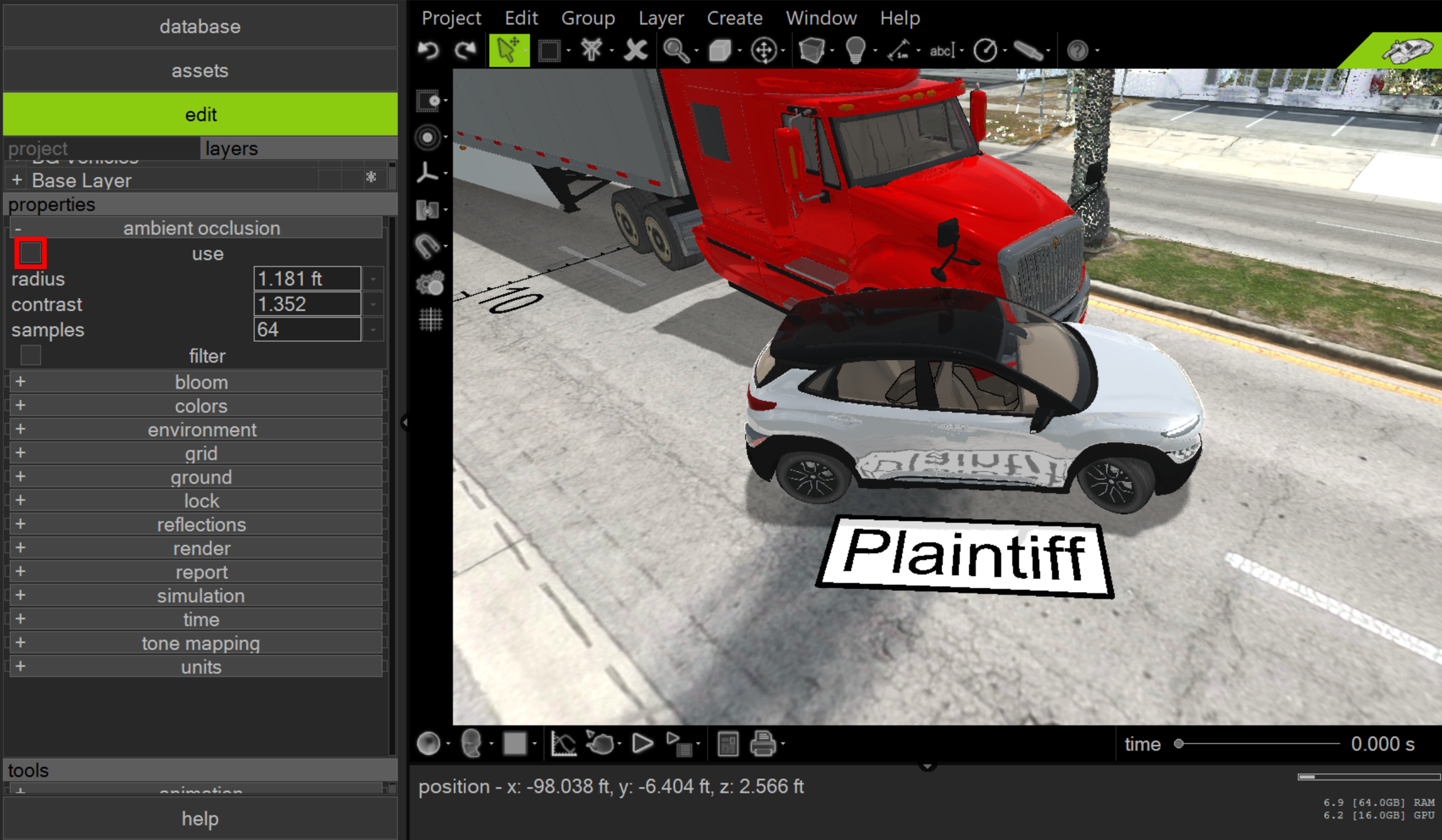
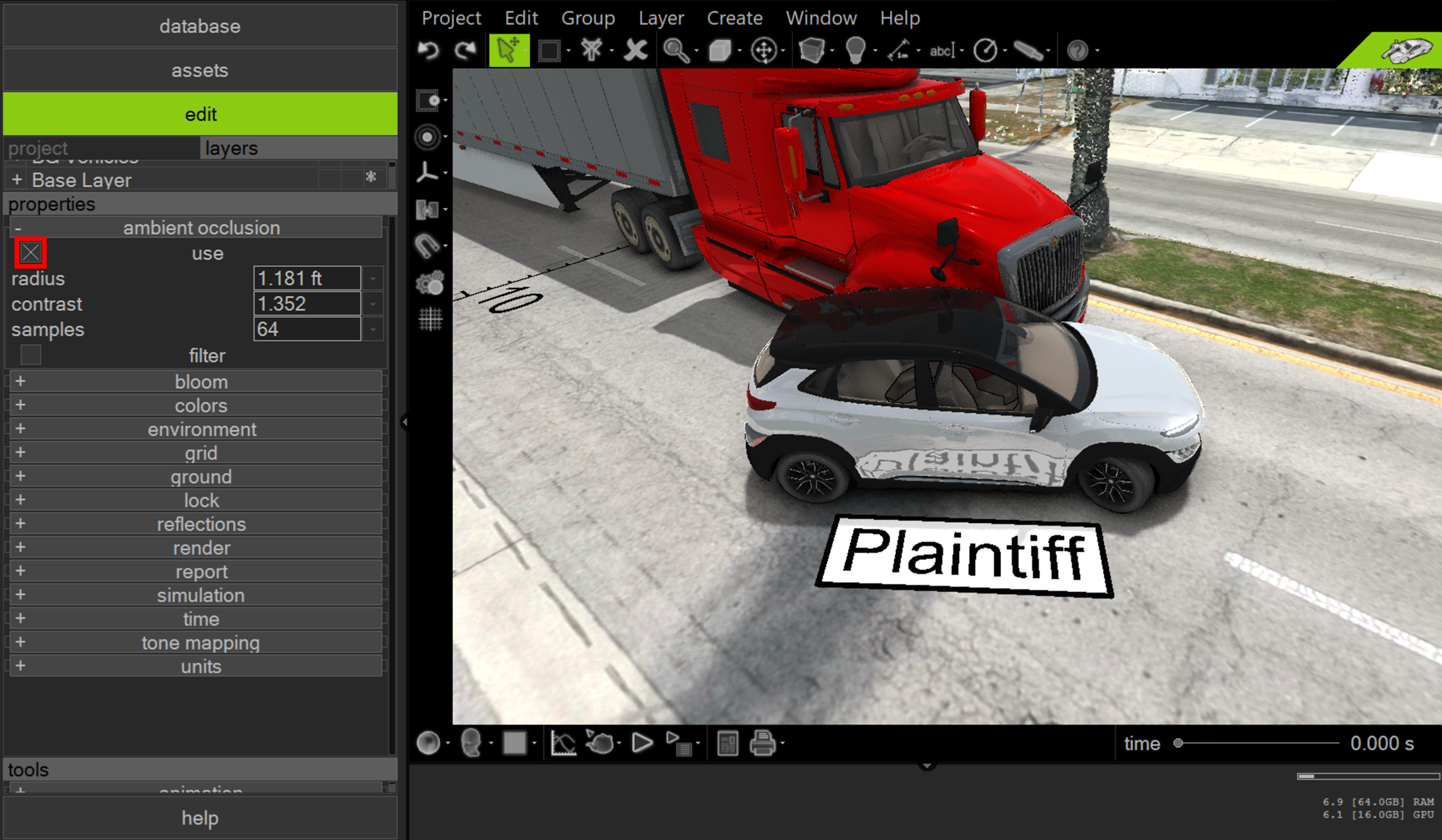
Radius: Sets the geometric extent of the effect.
Contrast: Sets the contrast of the effect.
Samples: Sets the level of detail.
You may need to reduce the number of samples if your system becomes sluggish due to enabling this feature. The “filter” option allows for the application of a noise filter, enabling the use of lower sample values without loss of visual quality.
The video below demonstrates the effects of this setting.
Properties > Reflections
Another project setting worth keeping a close eye on is found in the "reflections" menu. Rendering reflections in 3D graphics significantly enhances the realism and immersion of a scene. They assist in conveying the texture and properties of objects, adding depth and dimensionality. Reflections are crucial for creating realistic environmental interactions, such as displaying the surrounding landscape on reflective surfaces, thereby improving the viewer's sense of presence within a virtual space. Veterans of Virtual CRASH software are undoubtedly familiar with offline (CPU-based) rendering in skylight and direct light, which simulates the behavior of light rays reflecting off surfaces. While offline rendering remains an option in Virtual CRASH 6 (with enhancements), the true power of Virtual CRASH 6 lies in the Lightspeed Realtime Render Engine.
In the initial release of Virtual CRASH 6, reflections are based on a "screen space" method. This method works by tracing rays in screen space to determine which visible pixels should reflect off reflective surfaces, effectively reusing the rendered pixels to create dynamic, realistic reflections based on the viewer's perspective. However, it's important to note that this method can only reflect objects that are currently visible on the screen, potentially omitting reflections of objects outside the camera's view.
To access the reflections menu, look under "properties." Toggle "use" to enable real-time reflections of objects in your scene (note this does not affect sky reflections). Back face will allow the back side of polygons to create reflections even if the front side of the polygons cannot be seen by the camera. This is a great way to fill in gaps in reflections if the front faces of a given object are technically not visible to the camera. Noise allows additional noise to be added to reflections to mask any unwanted visual artifacts from the reflection method by extending the reflections out across more pixels. This setting also helps mask out the location where reflections end at the screen’s edge. Samples sets the reflection level of detail. Filter denoises, or smooths pixelated reflections. These settings should be adjusted from project to project to ensure you obtain the necessary visual quality for your production. The video below illustrates the effects of these various settings.
Note, these settings do not have an effect on offline rendering via direct light or skylight.
Properties > Colors > Background Color
The “background color” option controls the ground and sky color in the orthographic views (discussed in chapters below) and the sky colors in Contours, Wireframe, Hidden Lines, and Flat view modes (the preview modes are described in chapters below).
Properties > Colors > Foreground Color
The “foreground color” option controls the appearance of certain objects in the project workspace. For example, it controls the contour line color for objects displayed in flat, smooth, and texture draft preview modes (discussed in chapters below). Foreground color also controls the vertex color when in vertex select mode (discussed in chapters below).
Colors > Selection Color
The “selection color” option controls the appearance of the bounding box for selected objects, and the color of selected vertices, lines, and faces for 3D objects.
Here we see both the bounding box and selected polygon faces highlighted in selection color of green. When working with red objects, you may find it desirable to work with a different selection color (red is the default color) to make object manipulate (modifying vertices or faces) easier to see.
Properties > Grid > Grid Spacing / Major Lines Every
The grid line visibility can be enabled using the grid line visibility toggle (see below). The toggle can be found in the side or upper tool bar, depending on which theme is being used, or by going to Window > Show/Hide Grid in the menu bar. In the “grid” properties menu, you can control the grid spacing – that is, the distance between all neighboring grid lines (major or minor). “major line every” controls the frequency with which major grid lines are drawn.
Grid line and grid point snapping can be enabled by left-clicking the magnet icon in the side or upper tool bar, or by going to Edit > Snaps Toggle [Alt+S]. Use the snaps toggle menu to select which snapping options to enable.
Properties > Report > Decimal Places
The "Report > decimal places" setting is a global option in the software that determines the default precision (number of decimal places) for numerical data displayed in various features. This setting specifically affects:
Distance Line 2D: The precision of distance measurements in 2D.
Distance Line 3D: The precision of distance measurements in 3D.
Dynamics Info: The precision of numerical data related to object movement and interactions.
On-Screen Dynamics Info: The precision of dynamics-related data shown directly on the software interface.
Dynamics Report: The precision of numerical data in the reports generated for dynamics.
While this is a global setting, it's important to note that you can override it for individual instances of these tools if you need different levels of precision in specific cases.
Other options in the report menu are discussed in chapters below.
Properties > Units > velocity / metric / mass
To change the units displayed in Virtual CRASH 6, go to the project properties menu and open the “units” menu. Use the “velocity” dropdown menu to choose the unit for speed. Use the “metric” dropdown unit to choose the unit for distance/length. Use the “mass” dropdown menu to choose the unit for mass/weight.
Post-production Properties
Virtual CRASH 6 includes post-production functionality which will allow you to fine-tune the look of your visuals without needing to make adjustments to materials or lighting within the project. In many ways, ambient occlusion could also be considered a post-production adjustment.
Properties > tone mapping
Open the “tone mapping” menu under “properties” to find the gamma, exposure, and pure white inputs. Gamma modifies a scene’s apparent brightness, ensuring details are clear in both bright and dark areas without changing the overall balance. Exposure adjusts the overall light level in a scene, influencing how bright or dark the image appears. Pure white determines the maximum brightness for details to be displayed as white, helping to maintain contrast without losing information in the brightest parts. Enabling “shades of gray” will switch to black and white mode.
Properties > bloom
The "bloom" effect mimics the way real-world light diffuses to create a soft glow around objects with emissive lighting enabled in the scene. This effect eliminates the need to enable the volumetric source for a “halo” effect.
Below we demonstrate these various settings.
These settings are further illustrating in the below gamma versus exposure matrix.
Mouse Cursor Controls
In Virtual CRASH 6, you can find the mouse cursor control types under the Edit > Tools menu, by using the upper icon bar, or pressing [F2], [F3], or [F4] on the keyboard (see below).
Edit > Tools > PAN
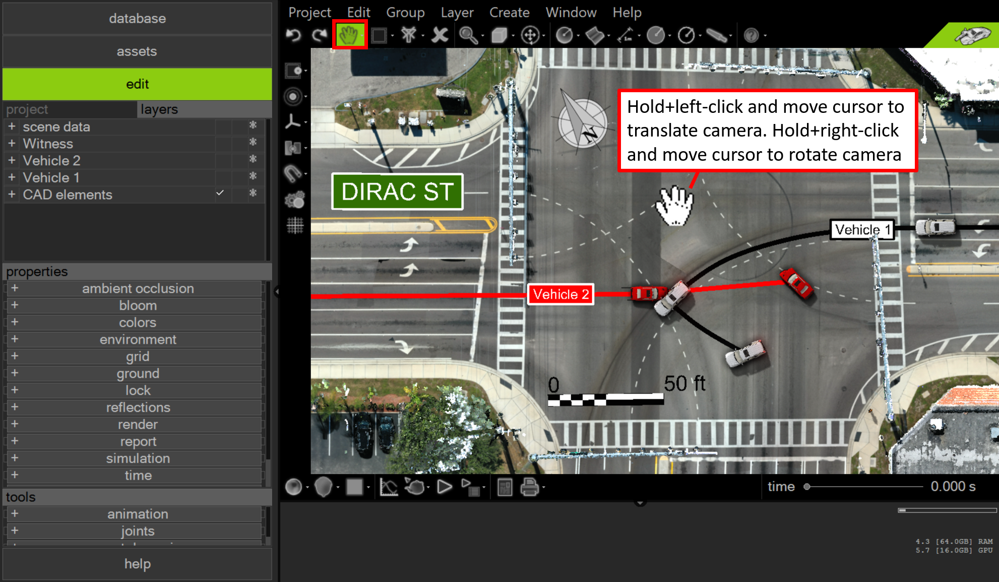
In “Pan” mode, you can change the interactive view without selecting objects. Pan mode is the default mode upon launch of Virtual CRASH 6.
While in Pan mode, hold+left-click and drag the mouse cursor to translate the camera. From the top-down orthographic view [NumPad5], hold+right-click and drag the cursor right or left to rotate the camera. In perspective view, hold+right-click and drag the cursor in any direction to rotate the camera. Note that, regardless of any unfrozen object underneath the mouse cursor, it is impossible to interactively select it within the workspace while in Pan mode. This feature ensures safe navigation through complex scenes and simulation scenarios without the risk of causing unwanted adjustments or modifications due to left mouse clicks.
In order to interactively select, translate, or rotate objects within the project, you’ll need to be in either “Select And Move” [F2] or “Select, Move And Manipulate” [F3] cursor control mode. These are described in more detail below.
Edit > Tools > Select and Move
“Select and Move” allows the user to select, move and rotate an object or multiple objects simultaneously. It also allows the user to move and rotate the interactive camera view. This function is enabled by left-clicking on "Select and Move" on the toolbar or by using hotkey [F2].
After the "Select and Move" feature is enabled, the mouse cursor changes to the shape of an open hand when hovering over areas where no selectable object is present, such as empty parts of the scene or when the cursor is over frozen and/or hidden objects such as vehicles and images.
If the mouse cursor hovers within the bounding box of a selectable (not frozen or hidden) object, the cursor changes into the shape of a cross. If the mouse cursor is hovering over multiple objects, Virtual CRASH will cycle through them as the user left-clicks.

Your selection will be confirmed by a bounding box appearing around the selected object(s). The object name(s) will also be highlighted in the project or layers menu.

To deselect an object, simply left-click on an empty part of the workspace, use alt+left-click on the select object, or right-click on the selected object’s name in the project or layers menu.
Multiple unfrozen and unhidden objects can be selected simultaneously by using ctrl+left-click either directly in the workspace or on the object names in the project or layers menu.
TRANSLATING OBJECTS
To translate an object within the scene, left-click on the object to select it. Move the mouse cursor near the center of the object bounding box and the cursor will change to crossed-arrows. Hold down the left mouse button and move the object to the desired location (see below).
ROTATING OBJECTS
To rotate an object in the scene, move the mouse cursor to the edge of the object until the pointer changes to a circled-arrow. Hold down the left mouse button and rotate the object to the desired position (see below).
Edit > Tools > Select, Move And Manipulate
This cursor control extends the functionality of "Select and Move". When using this feature, selected objects will also typically include additional 3D manipulators with which you can use to modify their properties.
For example, the control vertices of the selected spline curve shown below become visible when the spline curve is selected in the “Select, Move And Manipulate” cursor control mode. This cursor control can also be selected by left-clicking the icon on the toolbar or keyboard shortcut [F3].
“Restrict To” Modes
Sometimes it is preferable to manipulate object position with precise control over the translation direction. This can be accomplished by enabling one of the “Restrict To” options. To enable on of the many “Restrict To” options, use the upper tool bar menu drop down shown below.
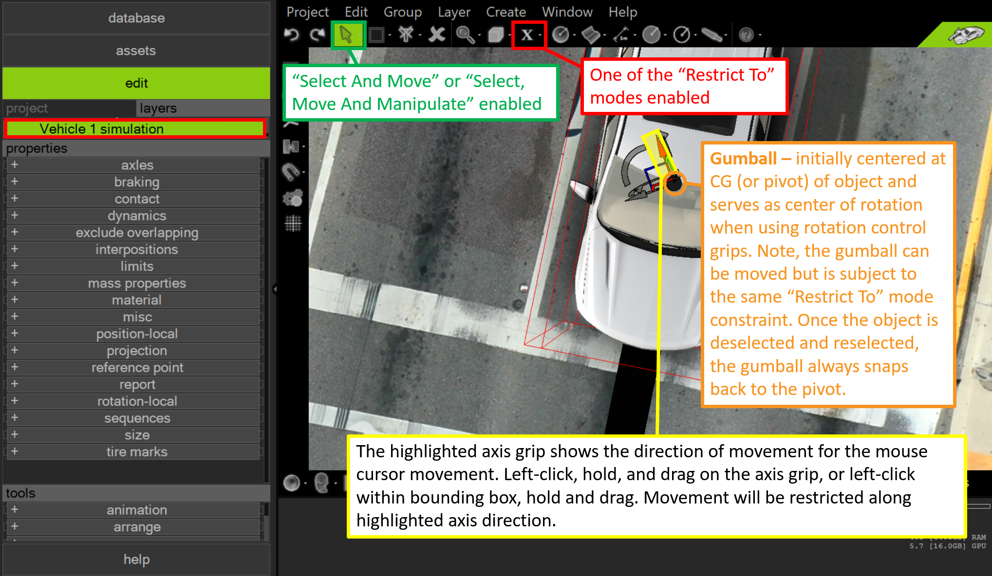
Once a “Restrict To” mode is enabled, you will see the gumball, translation, and rotation control grips become visible (see below).
It is often more natural to use the translation and rotation control grips as defined in the vehicle or object’s local “local” frame. To switch the control grips to local, use the toggle in the side tool bar shown below. Note, the rotation control grips naturally set yaw, pitch, and roll when in “Axis Local” mode, whereas in “Axis World” the rotation controls set rotation about the global x, y, and z axes.
Once the translation and rotation controls are visible, you can hold+left-click and drag directly on the grips to translate and rotate. Note, if you hold+left-click and drag within the bounding box rather than on the control grip, the mouse control will correspond to whichever “Restrict To” mode was selected in the dropdown menu.
When rotating with the "Restrict To" rotation control grips, the axis of rotation is defined relative to the gumball itself. The gumball's default position is at the object's pivot location, but it can be moved by hold+left-clicking and dragging. Note, gumball movements are restricted by whichever "Restrict To" mode is selected. For example, if "Restrict to X" is chosen, the gumball can only move forward and backward along the x-axis. To reset the gumball to the object’s pivot point, simply deselect and then reselect the object.
If you wish to adjust a rigid body object's initial z-coordinate, roll, or pitch angle using the "Restrict To" control grips, you'll need to first disable "auto align to plane" in the miscellaneous menu. "Auto align to plane" will reset the wheel positions and vehicle orientation (excluding yaw) anytime the vehicle is moved with the mouse cursor, including when using z, roll, and pitch controls. To prevent this reset, simply disable this option.
Once you are finished with the translation and rotation grips, you can hide them (along with the gumball) by using the "Restrict To" dropdown menu and selecting "Move And Rotate" (or by using the hotkey [0]). This is often desirable because the translation and rotation grips, as well as the gumball, can often overlap on the screen with other manipulators and controls, interfering with other workflows.
Drawing 2D Shapes
2D shapes, such as lines and curves, can be introduced into the project by using the dropdown menus from the upper tool bar (see below), or by going to Create > Shapes 2D or Create > Shapes 2D Filled in the upper menu bar. The sequence of mouse cursor movements and clicks required to make each shape will depend on which shape has been selected. Remember to right-click to finish the command altogether or else the command will repeat with the next left-click of the mouse. This may be desired, for example, if you are drawing a row of skip lines in the center of a road, but other times the repeat draw feature may be undesirable.
Below we add a line object to depict a tire mark. After selecting the line object from the 2D shapes dropdown menu, left-click on the starting position for the line and hold, drag the mouse to the final position for the line and release. Right-click to terminate the line draw command, otherwise you will continue drawing lines. If you are in “Select, Move And Manipulate” [F3] cursor control model, you will then be able to see the line’s control vertices (yellow dots). These control vertices can be moved interactively (hold+left-click and drag) to adjust the line’s orientation. The line’s attributes can be modified in the “line” menu in the left-side control panel. Many of these attributes can also be accessed by right-clicking within line’s bounding box with cursor control either in “Select And Move” [F2] or “Select, Move And Manipulate” [F3].
Creating various 2D shapes is discussed in more detail in the chapters below. You can also learn more about creating 2D shapes with the Virtual Tutor: help > shapes.
Organizing Assets using the Layers Menu Display
You can switch from the project menu display to the layers menu display view by left-clicking on the “layers” button (see below).
The layers menu display may be preferable for ease of organizing project assets. To create a layer, go to Layer > New Layer in the menu bar. Note, if you have an object already selected in the project, using Layer > New Layer will automatically place the selected object into the new layer. If you wish to create a new layer without placing an existing object into it, first deselect all objects (alt+left-click to deselect an object or left-click in an empty section of the project space while in “Select And Move” or “Select, Move And Manipulate cursor control mode), then use Layer > New Layer.
To change the layer’s name, left-click to expand the “misc” menu in the properties menu, then left-click in the name field and type whatever name you wish to use and press “enter”.
Once a new layer is created, left-click in the box next to its name (see below) to make it active. Once a layer is active, any new object placed into the project will be automatically placed into the active layer. You can left-click the “+” symbol to expand the layer to see its contents. Press “-” to hide the layer’s contents.
You can move objects between layers by left-clicking in the box next to the target layer to make it active. Next, select the object or objects (ctrl+left-click or left-click and drag to multi-select) to be moved. Finally, go to the tools menu and expand the “arrange” submenu. Left-click “send to current layer” (see below).
You will now see the selected objects moved to the active layer. Again, new objects placed into the project will be automatically placed in the active layer.
You can rearrange graphical elements (text, 2D shapes, and images) within a layer by selecting the given element and left-clicking the desired option in the tools > arrange menu. In the example below, our text is beneath the black line (in red circle below). This can be fixed by selecting the text object and left-clicking “bring to front” in tools > arrange.
Below we see our text element now appears over the black line.
Note, the tools > arrange menu options set display priority based on their order within the project menu display, regardless of what layer the objects are in. The order in which layers appear within the layers menu display can also be modified using the tools > arrange menu options. This will rearrange the display priority of all objects within the selected layer simultaneously.
Hiding Layers
To hide a layer, left-click in the middle box next to the layer’s name.
A dark mask icon will appear in the box indicating the hide property has been activated. Here we hide the layer containing Google imagery data to create a diagram more suited for printing physical copies.
Note, hiding the layer will hide all of the layer’s contents. This can be seen by expanding the layer.
This will also hide any of the layer’s contents in the project menu view. This is indicated by a light mask icon. To unhide the layer’s elements, you will need to return to the layers view and left-click on the dark mask icon to disable the hide layer property.
You can separately hide or unhide an individual element within a layer by toggling the mask icon next to its name either in the layer display or project display menu.
Freezing Layers
To freeze a layer, left-click in the right side box next to the layer’s name.
A dark snowflake icon will appear in the box indicating the freeze property has been activated. Here we freeze the layer containing Google imagery data. Freezing such data is recommended as it prevents the possibility of accidentally moving the underlying aerial imagery after the diagram graphical elements have been introduced to the project.
Note, freezing the layer will freeze all of the layer’s contents. This can be seen by expanding the layer.
This will also freeze any of the layer’s contents in the project menu view. This is indicated by a light snowflake icon. To unfreeze the layer’s elements, you will need to return to the layers view and left-click on the dark snowflake icon to disable the freeze layer property.
You can separately freeze or unfreeze an individual element within a layer by toggling the snowflake icon next to the element’s name either in the layer display or project display menu.
Organizing Assets using the Project Menu Display using Groups
It is not necessary to use the layers menu display to organize assets. You may prefer to simply use the project menu display (this is the default display mode). To organize assets in groups, first select all assets to be placed into a group, then go to Group > Group (see below).
Then rename the group object as needed in the “misc” menu.
To access elements within a group, left-click to open the group object folder, then left-click on the element.
Note, items within a layer can also be grouped.
To eliminate a group, go to Group > Ungroup. When a group is eliminated, all objects are returned back to the project or layer menu display as ungrouped.
Groups can be quite useful in Virtual CRASH 6, but they do have two important limitations. First, you cannot add elements to or remove elements from an existing group. To add or subtract elements, you must Ungroup the current group, then regroup the new list of elements. Second, groups can only be composed of like objects. For example, you cannot group a 3D vehicle object with 2D graphical elements such as curves. Because of these limitations, it may be more desirable to arrange your project’s assets using layers.
View Layout
You can adjust the view layout in Virtual CRASH 6 by adding more view panes. You can find the view layout icon in the lower tool bar or by going to Window > View Layout in the menu bar. Left-click on the preferred option from the view layout menu.
Once the view panes are visible, hover your mouse cursor over the boundaries between panes, left-click, hold, and drag to adjust the size of each pane as needed (see below).
Left-click inside of view pane to adjust its other properties. You will know the pane is selected because you will see a bounding box around its frame (note the selected lower right pane below).
Camera View
Once the pane is selected, go camera view selection menu in the lower toolbar (see below), or go to Window > Views to select one of the orthographic views (top, bottom, right, left, front, back) or perspective. Note, each view pane can have its own camera view. Displaying simultaneous camera views can be very useful for 3D modeling. Left-click or right-click to work within a given pane (note, right-click is the safer method because it eliminates the possibility of accidentally selecting an object within pane at the same time).
Real-Time Render Mode
Once the pane is selected, go to the real-time render mode selection menu in the lower toolbar (see below), or go to Window > Render Mode to select one of the render modes (hotkeys are shown in image below). Note, each view pane can have its own render mode. “Contours” can be very useful for aligning vehicles at impact as it allows you to see through the vehicle volume. “Wireframe” and “Hidden Lines” can be useful for understanding the details of a mesh’s geometry at a glance. “Flat”, “Smooth”, and “Smooth + Texture” can be great for diagrams and presentations
Adaptive Toggle
The Render Mode menu shown above has an “Adaptive” toggle. Left-click on this toggle to enable it. When “Adaptive” is enabled, the draft mode will automatically switch from whatever mode is currently selected (such as flat or smooth), to contours mode whenever you interactively change your current view. This may be preferable in cases with many high polygon count mesh objects, which could slow your pace of project development due to your graphics card refresh rate. Simply disable the toggle if you no longer need this feature.
Here we see the preview mode change to Contours as we move our camara.
Lag in Screen Refresh Rate
If you're noticing significant performance lag while building your project in “Smooth + Texture” [Ctrl+7], try using one of the other modes such as “Texture” [Ctrl+6] or “Smooth” [Ctrl+5], or enable Adaptive. Once you’ve finished building your project, you can still create your final visuals in “Smooth + Texture via the animation menu interface, print template tool, print tool, or Project > Export.
Object Selection Types
You can use the object selection type dropdown menu in the upper tool bar to select subcomponents of your vehicle or 3D object (see below). Object (the default mode) selects the whole object when selected.
If, however, you wanted to select the vertices of the object’s mesh to modify its geometry, left-click the “Faces” selection type (or press Shift+F) .
With a single face or group of faces selected, you can now easily impart crush damage to the vehicle’s mesh (see below). This type of 3D object manipulation and customization is discussed in the chapters below.
Tags: Selecting objects, select objects, moving camera, move camera, panning, pan camera, rotating objects, rotating cars, rotating vehicles, rotate vehicle, translating objects, translating cars, translating vehicle, translate vehicle.
© 2024 Virtual CRASH, LLC. All Rights Reserved