Blog Post | Simulating Direct Wheel Impacts, Curb Trips, and Roll Torque Resistance
Post updated 1/21/2020.
Volumetric Lighting
Included in Virtual CRASH 4 and 5.

Because impulses are only exchanged upon overlap of the vehicle polygon meshes, cases where you want to simulate directly wheel contact may require a little more work; remember, the wheels in Virtual CRASH are not part of the vehicle polygon mesh, and so are not considered by the collision detection algorithm.
Method 1: Using an EES Impulse Object
The easiest approach is to simply use an EES Impulse object to apply an impulse exchange between interacting vehicles at the desired moment in time. To do access the EES Impulse object, go to Create > Physics > EES Impulse.
Now, hover your mouse over the first vehicle (you should see it change light-blue), left-click and drag to the second vehicle and release (you should see the second vehicle change to light-blue).
Now you’ll see your ees object placed in the scene.
Fine-tune the placement of the ees object (the impulse centroid) as needed for your case. Fine-tune the timing as well to select the moment in time when you would like the impulses to be exchanged. Note, you can enable deformation and use the depth of penetration value as with any ees object.
The benefit of directly inputting an EES Impulse object as shown here is that the starting-time for the depth of penetration clock can be set at any time independent of whether or not the vehicle polygons are interacting.
Method 2: Rigid Body Wheels
Another technique to solve this problem is to directly install rigid body wheels, which is shown in the video at the bottom of this Knowledge Base post found here.
Method 3: Extending the Vehicle Mesh
Another technique involves simply modifying the polygon mesh of your vehicle. This is shown below.
In the image below, we see the automobile running into the tandems of the trailer.
Because the wheels themselves are not part of the trailer’s polygon mesh, the Kudlich-Slibar model will begin looking for the impact event after the polygons of the blue vehicle’s front-end begin overlapping with the polygons of the trailer’s frame structure, which sits behind the wheels. The impulses are then exchanged at the time equal to the moment of first polygon mesh overlap + depth of penetration time (set in the ees menu).
To start first overlap at the time when the blue vehicle’s front-end first touches the wheels, you simply need to add an extension to the trailer’s polygon mesh. First, orient your subject tractor-trailer to yaw = 0. Now clone the trailer and detach it from the tractor.
Next, make two cylinder objects, and align them with the tandems.
Next, carefully place the cylinders behind the wheels.
Remove physics from the cloned trailer.
Next, using ctrl+left-click, select the two cylinders and the trailer and export this object as a vcm file, just as you would when creating a new vehicle model.
Next, drag and drop the vcm file on top of the original trailer object. Select “yes” to replace the current mesh with your new mesh which includes the two cylinders.
Here you see the new trailer model with two additional cylinder objects.
Using the same method shown in prior posts (here and here), we will now need to re-adjust the ground clearance of the trailer to account for the vertices which now extend below the original underside of the trailer. Create a new trailer object and align it behind your modified trailer. Use this new trailer (shown in yellow below) to help set the proper ground clearance value for your modified trailer.
Now that the polygon mesh of the trailer extends downward to sit behind the wheels, the mesh overlap detection will now begin when the front-end of the blue vehicle touches the trailer’s wheels.
Here you see the impulse centroid is now located at the tandems.
An animation of the tandem impact is shown below.
You can make modifications to the additional vertices on the fly if needed. This may be required on occasions where the extra cylinders inadvertently make direct ground contact during jounce. In such cases, you may want to adjust the bottom most vertices upward in z to prevent such direct ground contacts. Remember, if you do readjust the z-position of your additional vertices, you may need to re-correct the ground clearnace value for your modified vehicle.
Motorcycles and Bicycles
This same methods shown above can be used for direct impacts to motorcycle and bicycle wheels. In the case shown below on the left, the motorcycle has no front fender, and as the blue pickup drives past the motorcycle, no vehicle mesh polygons overlap, and so no collision is detected. On the right, a cylinder has been placed within the front wheel to allow overlap between vehicle meshes. In this case, a collision event is detected, and impulses are exchanged between the motorcycle and pickup. An EES Impulse object can also be used in this case.
Curb Trips
Although the tire model looks for terrain along the vehicle's local z axis, the sidewalls of the tires themselves do not interact with the terrain. Below you see as the van slides sideways, the z position of the driver side wheels move up as the contact patches move to the height of the curb (the curb was created using the extrusion tool and was turned into a terrain object using Create > Physics > Make Unyielding / Terrain from Selection). This happens without sidewall contact interactions with the terrain object. Sidewall contact can be approximated by using a friction zone of high drag factor to generate sufficient lateral tire forces needed to impart a large roll torque, or we can induce direct sidewall contact by simply extending the vehicle mesh as shown below.
Method 1: Extend Mesh
You can use the same technique shown above for direct wheel collisions to add polygon mesh behind the wheels of our van shown here in this side impact case. Below we see our van now tripping over the curb, where direct contact is occurring between the van’s modified mesh (with polygons sitting just behind the driver side wheels) and the curb terrain mesh.
An animation of the trip and roll event is shown below.
Again, you can fine-tune the additional vertices as needed.
Method 2: Using EES Impulse Object
As shown above, here, we can install two EES Impulse objects (one for each wheel) to create impulse interactions between the van and median. Once the impulses are created, their positions and timing parameters will need to be fine-tuned to yield the desired result.
Roll Torque Resistance using EES Impulses
Because tire-ground contact normal forces are applied at the center of the contact patches cause suspension forces to be applied to the vehicle directed along a vehicle’s local z-axis, occasionally a vehicle undergoing simulated roll may roll for an extra 1/4 roll due to lack of sidewall roll torque resistance. Adding roll torque resistance to prevent this extra 1/4 roll is analogous to increasing roll torque to cause curb trips as discussed above. To increase roll torque, you can either modify the mesh of the vehicle to add polygons behind the simulated wheels (as shown above) or use EES impulse objects (also shown above). In the video below, we demonstrate using EES impulse objects to apply impulses between the sidewalls and ground terrain.
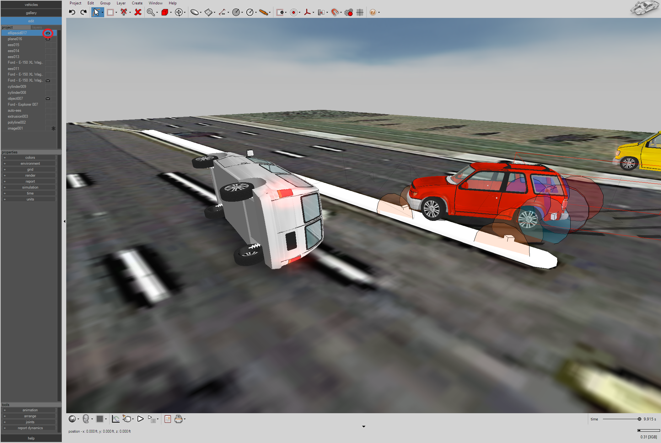
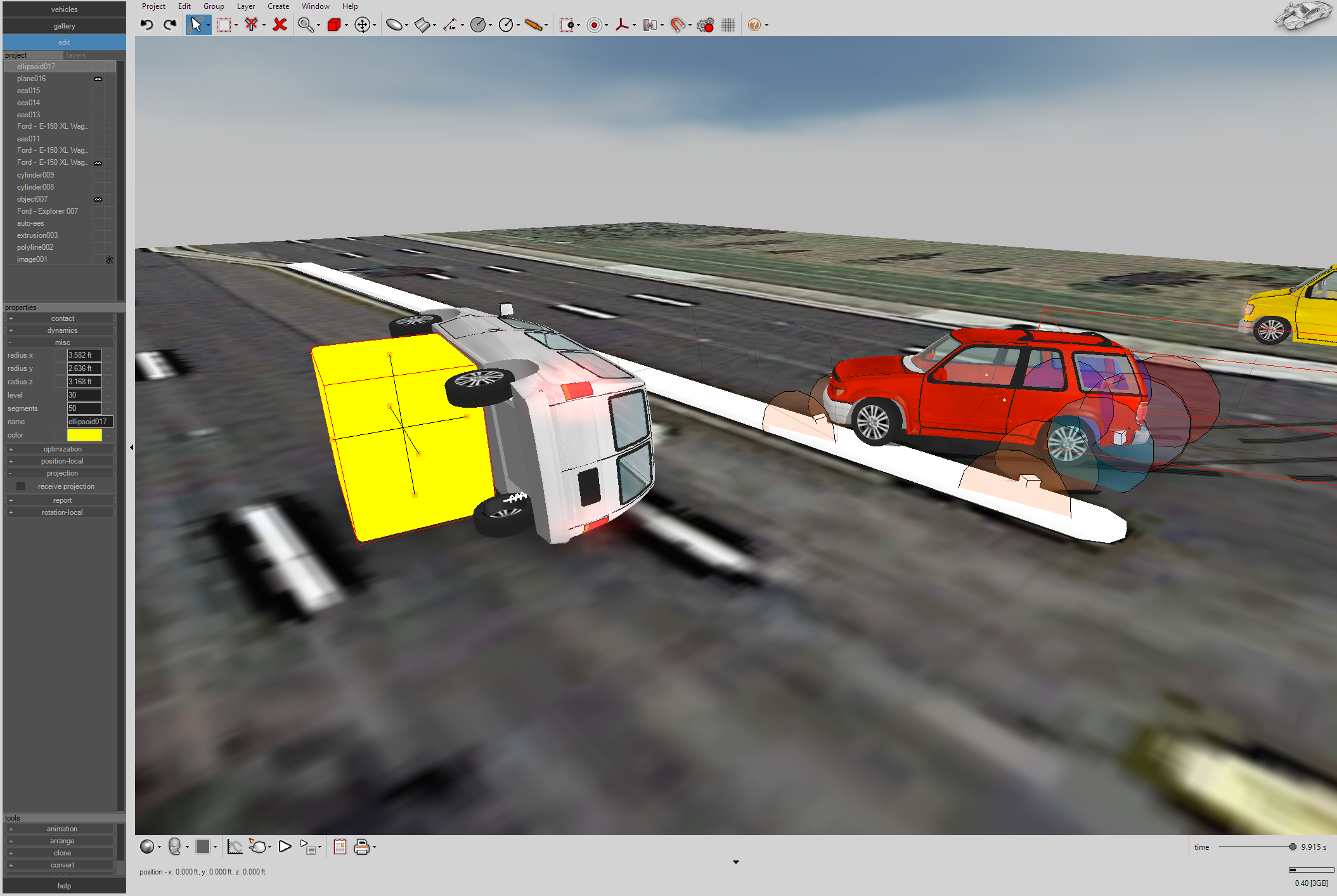
A “Brute Force” Approach
Another approach is to simply use a “stopper” to prevent additional roll. Below we place an ellipsoid (level = 30) into the scene. The ellipsoid is set to a terrain object and hidden from view. The contact interaction between the bottom of the van and the stopper is sufficient to prevent the extra 1/4 roll. If needed, by using the time-control boxes for position-local x,y, and z, we could move the stopper into position at the proper time then quickly move it out of the way if we needed to make room in the scene for other vehicles to pass near that same position.